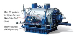
Oil refineries began using the precursor to API Plan 23 to seal light hydrocarbons that had to be cooled to prevent flashing and short mechanical seal life. Circulating devices were added to the seal design to circulate the process fluid through a shell and tube heat exchanger in a nearly closed loop. Decades later, API Plan 23 has proven to be the most effective way of sealing hot fluids in centrifugal pumps from a reliability, safety and economic perspective. These systems, extended from refining to power generation, are used widely today in water applications above 80 C, such as boiler feedwater services.
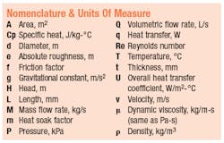
Detailed design calculations are not required in most cases where the application is a typical Plan 23, the mechanical seal contains a well designed circulating device, best practices are used for the layout and piping of the loop, and a well designed heat exchanger with known performance characteristics is used. But in some cases where one or more of these parameters is unusual, the application is hazardous, plant critical, or a due diligence study is advisable, then predictive calculations can be performed.
These calculations can be used as a baseline to determine if the mechanical seal is leaking, the Plan 23 tubing has been clogged or fouled, or the cooling water supply is insufficient. In each case, one will see a rise in the Plan 23 loop temperatures over time. If the performance parameters are measured in the field, this algorithm can be altered empirically for further comparison. Altering the overall heat-transfer coefficient is usually the best way to do this.
- The use of the log mean temperature difference (LMTD) used in determining heat exchange rate
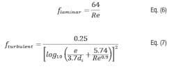
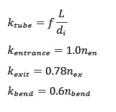
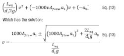
- The determination of the mass flowrate of the recirculated process fluid as a function of friction losses
- Some parameters are nonlinear functions, such as:
- Absolute viscosity as a function of temperature (exponential curve fit)
- Friction losses (empirical)
- Head-versus-flow function of the circulating device (curve fit)
In order to achieve accuracy, the following input parameters are required:
- The operating temperature of the process fluid,
- Liquid density and viscosity as functions of temperature,
- Dimensionless factors m1 through m6, as defined by Buck and Chen (2010),
- The head-versus-flow curve for the circulating device in the mechanical seal,
- Several dimensions of the seal cooler and interconnecting piping,
- The flowrate and temperature of the cooling fluid entering the seal cooler,
- Mechanical seal generated heat.
- At the end of this article, some rule-of-thumb values for quick "back of the envelope" calculations will be included. These are valuable when one does not have a detailed description of the mechanical seal, the seal cooler or pump construction.
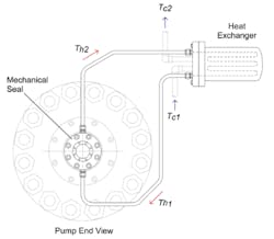
The physical system of a plan 23
Plan 23 loop flowrate
We will need a Plan 23 mass flowrate, Mhot, in order to calculate the rate of heat transfer, qcooler. This flowrate is generated by the circulating device in the mechanical seal. There are two basic types of circulating devices used for mechanical seals: radial circulating rings and positive-displacement pumping screws. Each has a characteristic curve as shown below. A radial circulating ring curve can be approximated by a second order curve as shown. A pumping screw curve is linear, as can be expected from a positive-displacement device.
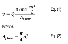
The flow velocity for a flow Q:W0 = −4.7e − 4, w1 = 0.0024,j0 = 1009, j1 = −0.441
(These constants must be consistent with the units specified above.)
The average temperature of the liquid in the Plan 23 loop, T, will be an iterative value as shown later.
where a1 and a0 are constants specific to the screw dimensions, fluid and speed. The flow generated by the pumping screw Qscrew will enter the interconnecting Plan 23 tubing, which has a flow area Aflow, calculated above.
The heat transfer system
There are two main sources of heat flowing into the Plan 23 process liquid—heat soak, qsoak, and seal generated heat, qseal. There is one significant source of heat removal—the seal cooler, qcooler. If these sources are at steady state then the heat transfer balance equation is:
qsoak + qseal – qcooler = 0
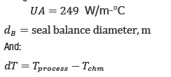
From Buck and Chen (2010)2, heat soak may be calculated as follows:Where Tprocess is the process liquid bulk temperature in the pump casing and Tchm is the average bulk temperature in the seal chamber. If the pump has a cooling jacket in front of the seal, it is acceptable to use qsoak = 0.
The seal generated heat, qseal, can be calculated using the method recommended by API 682 or obtained from the mechanical seal manufacturer. The heat transfer occurring across the heat exchanger can be calculated three ways, all of which are required in this method.
In these three equations, the subscripts hot and cold refer to the side of the heat exchanger containing the process fluid and the side containing the cooling liquid, respectively. The dT values are calculated as follows:The log mean area is used because the U value used for the heat exchanger is an overall heat transfer coefficient defined neither by the OD nor the ID of the tubes:
The overall heat transfer coefficient, Ucooler, can be calculated using several different empirical formulas, but one can obtain good accuracy by using curve fit functions or singular values obtained through testing. (520 W/m2-°C is a reliable value to use for modern seal coolers supplied by seal manufacturers.)Now we have the system of equations that govern the Plan 23 flow and heat transfer relationships. Unfortunately we cannot solve for the unknown temperatures Th1, Th2 and Tc2 because of the nonlinear log mean temperature equation for dTLM. We cannot solve directly for the mass flowrate through the system because the viscosity and density terms in the Reynolds equation are functions of the unknown temperatures and the nonlinear expression for the friction factor fturbulent used if the flow is in the turbulent regime. But several methods of solving a system of nonlinear equations exist. Most methods use a convergence criterion, which defines when a solution has been found. For our problem, one could keep guessing at Th1 until Eq. (15) has been satisfied to within 0.5 percent or so. Using the Solver function in Microsoft Excel is one of the easiest ways to solve this system of equations (see "Solution Example" sidebar).
Quick calculations
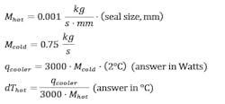
The following values and calculations can be used for simple hot process water analysis where many of the detailed variables above are unknown. This method is useful for troubleshooting applications in the field or sizing heat exchangers or cooling water requirements for budgetary proposals:
The actual loop temperatures, Th1 and Th2, will be functions of seal generated heat and heat soak (neither of which are measurable in the field) but should each be between 30 C and 50 C, and the dThot should be between 2 and 4 Δ°C.
The results of the quick calculations are:References
- See McKeon, B.J., C.J. Swanson, M.V. Zaragola, R.J. Donnelley, and A.J. Smits. “Friction Factors for Smooth Pipe Flow.” J. Fluid Mech. 511 (2004): 41-44.
- Buck, Gordon S., and Tsu Yen Chen. An Improved Heat Soak Calculation for Mechanical Seals. Proc. of Proceedings of the 26th International Pump Users Symposium, Houston, TX, 2010.
John Merrill is the U.S. principal engineer for EagleBurgmann, a manufacturer of mechanical seals and sealing solutions. Mr. Merrill has been designing, installing, troubleshooting, and testing mechanical face seals and seal support systems since 1991. His market sector experience includes upstream and downstream oil and gas, mining, chemical production, biopharmaceuticals, fossil and nuclear power generation. Mr. Merrill currently serves as chairman of the Hydraulic Institute’s Seals Committee and participates in the Reliability Committee. He can be reached at [email protected] or 704 525-9672.
John Merrill
John Merrill is a principal engineer with EagleBurgmann and resides in Charlotte, North Carolina. He has worked in the seal industry since 1990. Merrill received a Bachelor of Science in mechanical engineering from the University of Tulsa and a Master of Science from Western Michigan University. He is an active participant in the Hydraulic Institute, API 682, and ASM International.
