Best practices for process instrumentation lines
Safety and accuracy are top priorities when measuring pressure, flow or level within a process stream. Proper measurement of these important characteristics depends on the proper functionality of each component within the process instrumentation loop, from the tap to the transmitter.
Transmitters often get the most attention. However, transmitters only provide accurate readings when they are receiving accurate inputs. Determining whether a process instrumentation loop is performing well depends on knowing the signs of poor performance across the entire system, including critical componentry that feeds results to the transmitter.
Many of the most common performance issues are related to overall design and layout, which can dramatically influence the final measurement. This article will walk you through a series of best practices that engineers and technicians can follow to optimize process impulse lines and their outputs.
Know your system
First, it is helpful to form a strong understanding of the most important components in a process instrumentation line (see Figure 1 for a standard diagram) and the best practices for each: the process interface valve (PIV), impulse lines and the manifold.
Process interface valve (PIV)
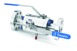
The PIV is the first valve off the process line. Traditionally, PIVs have been either single gate valves or ball valves. Both choices remain in use today, but the double block-and-bleed valve (DBB) has more recently been found to be the best solution for PIV applications.
A DBB can be fabricated and assembled from three separate valves or can be purchased as a single, self-contained unit — reducing size and weight. Self-contained DBB designs are appropriate for all fluids but are especially beneficial for systems with higher viscosity.
Impulse lines
Impulse lines connect the PIV to the manifold and transmitter. Their purpose is to convey the precise process conditions to the transmitter for analysis.
Proper impulse line configuration can help prevent corrosion, scaling and plugging; reduce leak points; and maintain temperature within a desirable range. The first two benefits can be achieved by using tubing and tube fittings made from an appropriate stainless steel alloy, as opposed to carbon steel pipe and threaded connections. Stainless steel tubing can be bent and shaped, which reduces the number of mechanical connections. When connections are necessary, two-ferrule, mechanical-grip-type tube fittings will not back off with thermal cycling or vibration, unlike traditional tapered pipe threaded fittings.
Maintaining a desirable temperature can be achieved by heating and insulating the impulse lines. This is accomplished by manually field-tracing tubes or by purchasing pre-insulated tubing. Pre-insulated bundled tubing typically comes ready to install in coiled lengths, and it is important to follow the manufacturer’s instructions for sealing the insulation when splicing or cutting the bundle.
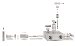
Manifold
Selecting the right materials
The building blocks of any process instrumentation line must be thoroughly considered by design and engineering teams. Depending on the process media and environmental conditions, PIVs, impulse lines and manifolds may need to be specified in certain alloys to meet the demands of the application.
For example, stainless steel — or a more robust metal alloy — is strongly preferred in many applications for its inherent corrosion resistance. It is not uncommon, though, to find carbon steel PIVs, piping and even manifolds in industrial plants around the globe. While acceptable in some low-moisture applications, carbon steel is susceptible to scaling, which can build up and flake away within the process instrumentation loop. This poses a significant risk — flaking carbon steel will flow downstream in the system and can lodge in a valve seat and obstruct positive shut-off. The result is an inaccurate transmitter calibration and readings, throwing off the accuracy of your entire process instrumentation loop.
It is a best practice to avoid carbon steel in most instrumentation loop applications to ensure that scaling and flaking are not interfering with operation. Instead, selecting higher-performing steel alloys can help ensure ongoing accuracy and reliability. Engineers and technicians can boost their knowledge on material selection from available training programs detailing the pros and cons of a wide range of alloys and materials for optimized selection.
Standardization and simplification
Design variations across multiple systems throughout a plant can complicate regular maintenance tasks. From system to system, technicians and maintenance staff must understand the intricacies of each, including which components and materials are used. Ordering replacement parts and making fixes can become a headache.
Instead, process measurement systems should be designed using a standardized, consistent set of criteria, including established budgets and allowances for downtime, maintenance and calibration accuracy. Standardization helps eliminate variation and potential confusion for technicians across systems.
For example, before standardization, a refining plant may have 30 different configurations for process instrumentation lines. After standardization, the same plant may have only six configurations, each containing the same basic components: a transmitter mount, manifold system and isolation valves. The primary variations might be the tubing runs and the type of isolation valves, which in turn depend upon the media, temperature, pressure and location of the transmitter or gauge. This helps simplify maintenance, installation, training and diagnostics for each system. Additionally, the plant can stock fewer replacement parts to help reduce overhead.
Another example of simplification is the close-coupled manifold. This elegant solution eliminates impulse lines entirely, eliminating the potential for clogs, leaks, temperature fluctuations and corrosion. In the close-coupled manifold, the PIV and manifold become one unit, with the transmitter mounted directly onto it. The entire assembly is attached to the process line, providing simplified access and operation.
Close-coupled manifolds have their limitations, however. They typically cannot be applied where the process line is operating at very high temperatures, due to transmitters’ sensitivity to high heat. Another limitation is access. Transmitters must be accessible for calibration, meaning they cannot be installed on process lines where technicians would have difficulty reaching them. Finally, close-coupled manifolds require a higher upfront investment — but that can be paid off in the long run by eliminating some common issues associated with impulse lines.
Achieving results
Proper system knowledge, materials selection expertise and standardization can help any design engineer enhance the accuracy of process readings — and therefore achieve better overall efficiency and profitability for any industrial plant. Securing the necessary knowledge and expertise comes from experience, as well as from working with expert suppliers who can help engineers optimize fluid system designs and plant operations.
Chuck Erml is product manager for Swagelok. He can be reached at [email protected].
About the Author
Chuck Erml
Chuck Erml is product manager for Swagelok. He can be reached at [email protected].


