Improved oil separator control strategies
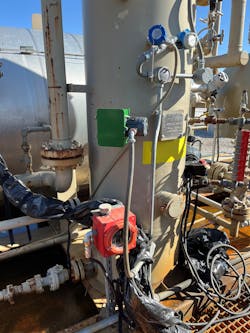
Stringent methane emission regulations forced the replacement of most natural gas-powered level controllers in oilfield separators. Many have been replaced with electric drive valves and on/off level control, which solves the emission problem but creates new issues with control and reliability.
This article discusses new level control technologies that are cost-effective and easy to retrofit, while providing only the required control precision. Just as important for these often-remote sites, installations are far more robust and easier on the equipment, allowing maintenance cycles to be extended significantly.
Oil separator level control
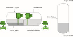
Oilfield three-phase separators are very common at well sites. They are a passive device that separates the mixed phase feed stream into gas, oil and water so it can be further processed and transported. As shown in Figure 1, a liquid/vapor mixture enters the left side of the vessel, and the liquids quickly disengage and fall to the bottom. The gas vapors exit via overhead piping and the liquids separate, with the oil floating on top of the water.
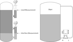
Figure 2 shows the instrumentation typically employed on a separator. The oil level is controlled with a level transmitter that maintains the top of the oil level below the weir, but high enough so that gas cannot escape down the oil pipe. It controls level by adjusting the oil outlet valve, which sends oil downstream for storage/processing.
Perhaps the most difficult measurement is the oil/water interface. The level interface measurement must detect the oil/water interface and keep it roughly midway up the weir by throttling the outlet valve to drain water out of the bottom. If the interface is too high, water will cross the weir and be sent to oil storage. If the interface is too low, oil will escape out the water piping and be lost.
Historical solutions
Most remote well sites lack compressed air, so a common solution for oil separator controls was to use the available natural gas pressure to power the necessary level transmitters, controllers and valves. This worked well but continuously emitted significant amounts of methane to the environment. Recent greenhouse gas regulations have eliminated this as an option, so many wellhead operators have been forced to consider other alternatives.
One obvious solution is to install some kind of air compressor at the site and use the existing pneumatic instrumentation as is. This can work well for large well sites that have many instruments, but it is usually cost prohibitive for the more typical wellhead site that may only have one or two separators.
A commonly deployed low-cost option for small sites replaces the level transmitters with level switches and installs electric valves. This eliminates the requirement for compressed air, and the switches control level by alternately opening/closing the valves to crudely maintain level within a certain operating range. This option works but has significant limitations that impact long term maintenance and reliability.
On/off control can never reach steady state because level is rising when the valve is closed and falling when the valve is open. When the well flow is significant, the valve will constantly cycle open and closed, wearing it out quickly. This option also requires significant electrical power, which can be a problem at remote sites, which often rely on solar power. The inevitable and frequently required valve replacements cost money and results in lost production, and a failed valve can result in lost oil down the water line, or it can create problems in downstream gas and/or oil processing.
A better solution is to install a level transmitter and controller for each level loop. This approach modulates the valves to maintain a steady level, requiring little valve movement once a setpoint has been reached. Reduced movement extends the valve life significantly and uses far less energy. Unfortunately, the additional controllers add significant cost to the installation, but there is a better alternative.
Level detection technologies
During the course of oilfield separator retrofits, many users have tried a variety of different level measurement technologies. Guided wave radar works well, but it often requires major modifications to the existing vessel to add the required bridles or flanges (Figure 3). Differential pressure (DP) transmitters have also been tried, but they tend to plug over time. DP cells with dual diaphragm seals work well, but they are significantly more expensive than basic designs.
Displacer technology has historically worked very well in both level and interface applications, and it is particularly suited for plugging/coating environments. Unfortunately, a typical displacer utilizes a bridle arrangement similar to guided wave radar, raising equipment and installation costs.
A better alternative
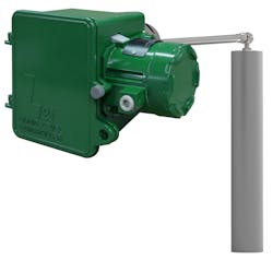
A much more cost-effective option has recently been introduced, and it solves many of the aforementioned problems facing oil separator retrofit design teams (Figure 4). The level/interface transmitter utilizes field-proven displacer technology, but the revised mechanical design allows the displacer assembly to be inserted through a 2-inch NPT or flange fitting on the side of the vessel. This arrangement often allows the transmitter to utilize existing vessel connections, dramatically reducing retrofit costs. This option is also much less expensive than a DP transmitter with dual diaphragm seals.
The device measures level or interface equally well, so it is particularly suited for oil separator applications, and it also eliminates the need for a separate level controller as the device performs this function onboard using an innovative technique, as explained next.
A typical level application employs a transmitter to detect the level, a control valve to regulate the level and some type of controller to compare the current level against a setpoint and adjust the valve position as necessary. That arrangement is expensive and works well when very tight level control is required, but an oilfield separator does not require this level of precision. Instead, the controller just needs to keep the level within an operating range, and ideally it needs to find a steady state so that the valves are not constantly cycled.
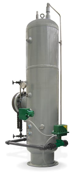
These goals can all be achieved by simply wiring the level transmitter to an electric valve (Figure 5.) The level transmitter is calibrated across a relatively short range, and its level signal is fed directly to the valve. As the level rises, the control valve opens, and eventually the level will reach a steady-state equilibrium where the incoming flow matches the outgoing flow. Should the inflow change, the level will change, driving the valve position until steady state is again reached. The combination of valve and transmitter will control the level within a narrow range without employing an external controller.
The ability to easily replace the level transmitter and eliminate the controller can make oil separator retrofits much less costly. The new arrangement also saves significant energy and control valve maintenance cost by minimizing valve movement during operation. If low-flow conditions are often encountered, the electric valve can be configured to automatically shut below a certain control signal. This keeps the valve from throttling at the seat, which is the condition where valve damage typically occurs.
Use cases
The benefits of continuous versus on/off control are significant, as shown with these use cases, all using the Fisher L2t Liquid Level Controller and the Fisher easy-Drive Electric Actuator solution.
An operating company in the Marcellus Shale area of the United States had been changing from on/off to continuous control using DP level transmitters. The continuous control worked well but the DP transmitters were routinely plugging and causing operational problems. A swap to the displacer-based L2t transmitters eliminated those problems and allowed the oil separator controls to operate reliably for long periods without any service at all.
Two operating companies in western Canada began replacing on/off controls with this solution on high-flow wells due to ongoing maintenance problems with the cycling valves. The retrofits were inexpensive as the transmitters were installed in existing vessel cutouts, and the new technology enabled continuous control that dramatically reduced service intervals and costs.
Conclusion
If you are experiencing maintenance problems with oil separator on/off controls, or if you are having problems with erratic and inconsistent level control, consider a displacer retrofit and the installation of an electric control valve. This cost-effective solution is easy to install, and it provides significant benefits via increased production and reduced maintenance costs.
Kurtis Jensen is a portfolio manager for Emerson responsible for product development, serving as an advocate and promoter of innovative technologies that benefit end users. He has over 40 years of experience in field service, system integration, asset management, cybersecurity wireless technologies and field instrumentation. He holds a BA degree in Business Administration and Management from Buena Vista University, and an MBA degree from the University of Dubuque.
Emerson
About the Author
Kurtis Jensen
Portfolio manager for Emerson
Kurtis Jensen is a portfolio manager for Emerson responsible for product development, serving as an advocate and promoter of innovative technologies that benefit end users. He has over 40 years of experience in field service, system integration, asset management, cybersecurity wireless technologies and field instrumentation. He holds a BA degree in Business Administration and Management from Buena Vista University, and an MBA degree from the University of Dubuque.

