Installation and maintenance diagnostics help speed commissioning and simplify ongoing support
In the fourth installment of this five-article series on advanced diagnostics we will examine what installation and maintenance diagnostics can detect about the infrastructure supporting a control system. As a quick review:
- In the first article of the series, we provided an overview of instrumentation diagnostics, with five ways they are used in process manufacturing environments.
- In the second, we focused on device diagnostics and what an instrument can tell us about its own condition.
- In the third, we took a deep dive into process diagnostics and the problems they can detect.
- In the firth article, we will look at some specific use case in more detail.
Now we will take a look at some of the most useful troubleshooting tools available, installation and maintenance diagnostics, and show how those capabilities are key to solving nagging instrumentation problems when using 4-20 mA loops (Figure 1). Sometimes the greatest help is having a tool to show where the problem is not.
Let’s unpack a hypothetical scenario and see how different diagnostic capabilities work together. Here is the challenge: a specific reading is showing in a control room monitor with a value that operators believe cannot be correct. There is a possible problem in one or more of these areas:
- A process issue is interfering with the reading, such as a clogged impulse line.
- The instrument itself is malfunctioning or is out of calibration and providing an incorrect value.
- Something has gone wrong with the host system, possibly the I/O card.
- A problem has developed in the wiring carrying the 4-20 mA signal.
The traditional method for dealing with such a situation is sending an instrument tech into the plant with a hand-held communicator to start taking readings from one end of the loop to the other. But given how few instrument techs there are these days, let’s see how advanced diagnostic capabilities can make troubleshooting much quicker.
- For cause one, we learned in Article Three that process diagnostics should be able to identify when a process-related issue could be developing able to disrupt the reading, or it can show that nothing odd is happening.
- For cause two, we learned in Article Two that an instrument with advanced diagnostics should be able to monitor itself and let the reliability team know if some internal problem is developing. More on that in a moment, but it can eliminate itself as a cause if it is working properly.
- Cause three is harder to pinpoint, but advanced diagnostics can still help. More on that in a moment as well.
- Cause four is where loop integrity diagnostics are a huge help.
As these solutions become more integrated and capabilities overlap, let’s revisit three typical solution approaches from actual plant experiences in the broader context to show how we work through the list above to eliminate the red herrings and find the root cause.
Combining device diagnostics with self-calibration
A technician beginning analysis of this problem would probably begin by verifying that the instrument is working correctly, with a first step making sure there are no messages indicating a fault in the transmitter. That is fine as far as it goes, but there is also the possibility that the instrument, while functioning properly, is simply out of calibration. If the instrument is a flowmeter, eliminating a calibration problem likely calls for taking the unit out of service and sending it to a lab, or at least an internal shop. This requires a process shutdown for removal, testing and reinstallation.
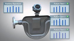
The device diagnostic concept can be extended to Smart Meter Verification, which provides deep information from Coriolis, magnetic and ultrasonic flowmeters. The flow transmitter uses on-board diagnostics to monitor key performance indicators continuously (Figure 2). Each flowmeter undergoes a diagnostic at the factory to create a “signature” of operational parameters. This test is repeated once the flowmeter is installed in its actual application under normal conditions.
The combined factory and installed signatures are stored in the transmitter, and real-time characteristics can be compared to the standard on a continuous basis. This does not replace normal calibrations, but it can make them far less frequent. Outside of detecting changes against the stored signature, there is little reason to suspect a problem. Consequently, Smart Meter Verification maintains measurement accuracy and meter integrity, reducing maintenance and calibration costs through early detection of issues.
The case study referenced in the earlier article was a wastewater treatment plant in the western U.S. that added Smart Meter Verification to its fleet of Rosemount 8750W Magnetic flowmeters. Using data provided by the upgraded transmitters, the frequency of flowmeter calibration was reduced from four times each year to fewer than once each year. This also helped verify the units were operating correctly when combined with routine device diagnostic checks.
Establishing and maintaining loop integrity
An instrument depends on flawless communication with the host system to provide an accurate process variable to control and optimize operation. With most plants using 4-20 mA with HART loops, this can get complicated since an instrument may depend on hundreds of feet of cabling through multiple marshalling cabinets. There can easily be a dozen terminations between the instrument and I/O card of the host system. Much can go wrong in between (Figure 1) with moisture, corrosion and inadequate maintenance interfering with proper operation.
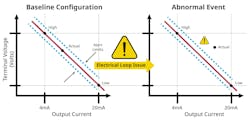
Emerson’s loop integrity diagnostic checks the wiring by following an automatic test routine after a new instrument is commissioned, and then periodically thereafter (Figure 3). It drives the terminal voltage to its low end and then reverses it to the high end. This constructs a line with some tolerable limits for variation. If the voltage and current relationship moves outside these limits, it can be set to trigger an alert.
This is a valuable tool to detect two common on-scale problems (Figures 4 and 5) due to wiring degradation or problems at the host system I/O.
This reminds us of the case study cited earlier where technicians at a major petrochemical manufacturer were battling intermittent device failures attributed to loop wiring insulation melting in its conduit. Replacing the wiring did not help, and managers saw no alternative to a full unit shutdown. Fortunately, a last resort, running the loop integrity diagnostic, revealed a floating ground due to an I/O card misconfiguration. The unit shutdown was avoided, saving the plant more than $3.6 million in estimated costs. This issue probably could have also been detected by the regular device diagnostics for the transmitter as they can also detect most ground problems, but loop diagnostics provided another approach.
Options for eliminating wires
As we have discussed, many instrumentation problems relate to wiring. So how do diagnostic capabilities relate to wireless environments? Let’s look at two main wireless approaches.
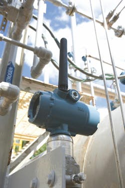
WirelessHART is the networking protocol that captures data from instruments, often without any wiring since many field instruments can be powered for years using in internal battery. Such is the case with Emerson’s Rosemount 3051S Wireless Differential Pressure Flow Transmitter (Figure 6). Data is sent to a gateway that interfaces with the host system using Modbus or Ethernet networks. WirelessHART- enabled instruments have many of the same diagnostic capabilities discussed here, and they add specialized communication analysis and diagnostics.
Use of WirelessHART must be an intentional strategy since it requires supporting infrastructure, namely a WirelessHART network. Such is not the case with the second option.
Bluetooth technology enabled instruments
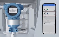
Bluetooth technology is a standard for short-range wireless communication between devices such as mobile phones, computers and other electronic devices. Options have been selected within the Bluetooth technology offering to make it suitable for industrial environments so it can be applied to field devices mounted in process manufacturing facilities. Using this approach, Emerson’s Secure Bluetooth wireless communication is being added to a growing variety of field devices as a method for easy configuration and viewing of information via the Emerson AMS Device Configurator.
So how does this work? Returning to the hypothetical example, all the diagnostic information from the instrument that would normally require a wired HART communicator to access can now be picked up via a smartphone or laptop. The technician does not have to open the transmitter or find the correct terminals in a marshaling cabinet. Simply standing within 50 feet of an instrument is sufficient to access all the HART diagnostic information. No additional infrastructure is required, and all the existing wiring operates as it always had.
This eliminates the need for opening anything, so no hot work permits or equipment shutdowns are needed, nor is there any need to climb to a transmitter that is difficult to access. Secure Bluetooth communications is also much faster than HART via wires for downloading information. This is an important improvement for companies using the diagnostic capabilities discussed here.
A multi-pronged tool
For instrumentation, the range of diagnostic capabilities is a multi-pronged tool to keep a process operating at its best. By monitoring status reports on individual instruments, process activity and automation infrastructure, it is much easier to determine when conditions are developing capable of interfering with effective production.
Adding Secure Bluetooth connectivity makes monitoring diagnostics even easier. Technicians can make plant rounds and check the status of instruments supporting Secure Bluetooth communications without needing to be at grade, interfering with any operation or removing housing covers. Any changes can be made very quickly, increasing productivity and potentially reducing downtime.
The ability to use diagnostic capabilities to confirm correct installation and troubleshoot problems can save much time wasted on guesswork. Fixing problems quickly and decisively depends on eliminating unrelated causes, thereby isolating the cause positively, so the right corrective actions can be taken, returning the plant to full production. The technologies discussed in this and prior articles provide the tools needed to realize these and other benefits.
About the Author

Kelly Albano
Product manager for Emerson Coriolis transmitters and software at Emerson
Kelly Albano has been with Emerson for over 12 years and is a product manager for Emerson Coriolis transmitters and software. She is focused on improving user experiences and guiding users through digital transformations. Albano holds an undergraduate degree in Environmental Engineering from University of Colorado at Boulder, and an MBA with a Marketing Management Certificate from Colorado State University.


