Taking the fight for flow capacity upstream with Rheo-Kinetic Fairings
Maximizing flow capacity of liquid through valves, pipes, instruments, pumps, heat exchangers and other equipment has been a long-standing challenge to designers. Limitations to flow capacity are generally influenced by static pressure of the flowing fluid, rheological properties and characteristics such as temperature, viscosity, surface tension, vapor pressure, presence of solids and the flow geometry, among other factors. The aggregate of these factors tends to drive designs in one or more directions to find a balance between cavitation prevention, pressure drop management and desired flow.
Extensive work in the design of control valves has resulted in several cavitation-limiting methodologies including cage trims1,2 and hardened materials to withstand the effects of cavitation3. In other equipment and applications, preventing cavitation or managing pressure drop through the device generally results in increased overall size where cavitation and increased pressure drop tend to occur. These techniques often result in objectionable increased cost due to the size of the equipment. Vanes, too, have been employed in elbows4 to manage the effects of pressure drop and cavitation.
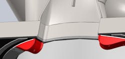
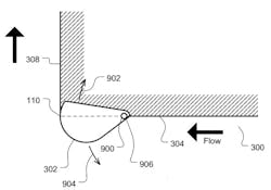
Artisan Industries Inc. has been developing novel methods to improve liquid flow in high-flow devices with complex flow geometries while combating these same issues – increase throughput with minimal affect on energy costs, while preventing cavitation damage. Using Rheo-Kinetic Fairings, a mechanical device or integral shape introduced to the flow field and attached to the boundary wall (Figure 1), the fight for flow capacity is taken upstream.
The Rheo-Kinetic Fairing shown in Figure 1 differs in principle from a vane in several ways, namely:
- A vane is designed to decrease the radius of curvature of the flowing fluid to hold it closer to the existing or desired geometry. Conversely, fairings seek to increase the radius of curvature.
- A vane does not contact the existing flow boundary (wall) but rather is suspended within the flow boundary when looking in the plane normal to the flow.
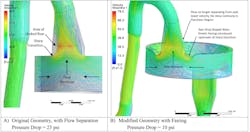
To demonstrate the effectiveness of Rheo-Kinetic Fairings, analytical studies were undertaken on a fluid management device containing heated hydrocarbons flowing at approximately 5,300 GPM. The equipment consists of areas where the flow is split into multiple paths and re-joined prior to exiting the device. In this example, the flow enters via 8-inch NPS Sch 80 pipe at approximately 37 ft/sec, is split into two flow paths around an annulus and is then re-joined in a pipe of the same size before eventually reducing to a somewhat smaller pipe and exiting the device. Entrance and exit regions to the annulus feature sharp corners prime for flow separation and pressure drop. Product capacity was limited by concerns over potential cavitation damage and legacy design constraints, which traditional mitigation techniques could not overcome.
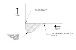
Initial CFD simulations clearly showed flow separation and Vena contracta affecting performance in the transition regions of the flow (Figure 2a). Introducing a tear-dropped Rheo-Kinetic Fairing (Figure 3) on either side of the exit region (Figure 2b), upstream of the flow, resulted in 16% drop in peak velocity and 56% reduction in pressure drop through the equipment. Within the transition region, the velocities decreased by closer to 40%, and there was virtually no flow separation present.
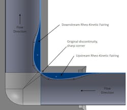
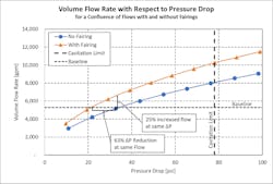
This analytical study only explored the use of Rheo-Kinetic Fairings in the region shown but additional studies have explored their use in other locations, i.e., upstream, downstream and in combination within the flow regime with similar benefits including tight radius elbows created by holes drilled normal to each other through a forging (as shown in Figure 4). When the precise shape of the fairing is optimized, i.e., adjusting the radii, length and protrusion into the flow, and the flow performance is characterized over a range of flow rates, the benefits become clear (as shown in Figure 5). It is believed that with careful selection of location and purposeful manipulation of the fairing shape, benefits beyond those represented may be achieved.
Equipment performance improvements can be seen in four ways:
- Increase of flow capacity by 25% before pressure drop penalties are incurred.
- Energy savings associated with lower pressure drop.
- Some combination of 1 and 2.
- (Or) Identifying the true hydraulic capacity by increasing the flow rate higher until the onset of cavitation.
The case of improvement #4 comes with some caveats as one should also consider unforeseen effects of higher flow rates. Depending on the application, entrained gas or solids will accelerate erosion, flow-induced vibration or vortex shedding could impart mechanical loads, which are difficult to predict and quantify, and other factors become more prevalent depending on the application.
The economic opportunities of the improvements shown in Figures 2, 3 and 5 become attractive if one considers the effect of pressure drop on energy consumption and the necessary power required to transport fluid. For the analytical example, assuming the equipment shown accounts for 35% of the system total pressure drop and calculating the required power5 by:
BHP = (GPM x H x SG)/(3960 x n) (1)
Where:
BHP = Pump break horsepower
GPM = Flow rate, gallons per minute
H = head loss, feet
n = Pump efficiency factor (assumed to be 0.85)
SG = Specific gravity (approximately 0.75 for this example)
Cutting the pressure drop of such a device by 50% would potentially reduce the pump energy cost by 17%.
The hydrocarbon application explored initially shows not only the benefits of small changes to flow geometries upstream of features causing undesirable flow performance but also the potential economic benefits in high-flow applications. Artisan believes that there are far-reaching opportunities for this technology where flow separation or cavitation may be a problem and has applied for a patent describing the present and other applications of the Rheo-Kinetic Fairings and their use. Protein processing, blood flow and other medical applications represent one such field. Another could include slurry flows and flows prone to fowling where eddies generally develop.
Artisan has also considered that Rheo-Kinetic Fairings with changing geometries may be of benefit. If the contour of the fairing is adjusted based on a set of parameters, i.e., differential pressure, dynamic pressure or other system parameter, a potentially larger envelope of flow enhanced benefits may be realized.
A couple of such examples follow:
In the case of slurry flows or solutions prone to depositing solids where accumulation on the wall may degrade performance, a Rheo-Kinetic Fairing may be used in conjunction with a bladder and differential pressure switch to inflate and break apart deposits much the way a de-icing boot on the leading edge of aircraft wings operate.
Consider a case in which a piece of equipment may need to operate efficiently over an extremely wide range of flow rates. An example shown in Figure 6 where the fairing may be hinged and movement resisted by a spring such that the profile is a function of the flow rate. Perhaps performance needs to be purposefully governed within a narrow operating window and operation below or above this window is undesirable.
Beyond fluid flow and management of flow, Artisan has also considered the potential applications within the measurement space where Rheo-Kinetic Fairings may pose some benefits to flow measurement in reducing losses through orifice meters or being used to purposely emit resonant tones under specified conditions, which could either be audible or detected by an electronic sensor and subsequently used to control a process.
Development and implementation of Rheo-Kinetic Fairings within a given application will have some challenges because of the nature of a protuberance into the flow. In the earlier application example, the fairings could easily be machined using CNC control and fastened to the equipment because there is access, and the geometry is relatively simple. Other applications may be more challenging, especially as the scale is reduced. With the increasing availability and lower cost of additive manufacturing, Artisan believes there is promise for the economics of implementations. Artisan is currently working on prototypes of Rheo-Kinetic Fairings in chemical equipment applications utilizing 3d printing to bring the fight for capacity upstream.
References
- Dr. Monsen, J., “Liquid Flow in Control Valves,” Technical Controls, date unknown.
- Roth, K.W., Stares, J. A., “Avoid Control Valve Application Problems with Physics-based Models,” Hydrocarbon Processing, August 2001.
- Stares, J., “Control Valve Cavitation, Damage Control,” Dresser-Masoneilan publication, February 2007.
- Beale, M. A., “Turning Vanes in Exhaust Duct Flow: Study for Energy Efficiency, Optimization and Pressure Drop Mitigation,” Naval Postgraduate School, Monterey, CA, 2014.
- C.C. Heald, “Cameron Hydraulic Data,” 19th Ed. Flowserve Corp.
For more information on Artisan Industries Inc., go to www.artisanind.com.
Peter Tavilla, P.E. | Director of Mechanical Engineering at Artisan Industries Inc.
Peter J. Tavilla is a registered professional engineer with a master’s degree in mechanical engineering and is the Director of Mechanical Engineering at Artisan Industries Inc. His experience spanning construction project management, R&D, sensors & controls, and global manufacturing through prior tenures with now Raytheon Technologies and Sensata Technologies. Mr. Tavilla has developed several class-leading product enhancements including patented technology stabilizing thermal accuracy of pressure switches. His current professional focus is pressure vessel & industrial machinery design and manufacturing. Mr. Tavilla is also currently developing flow improvements in industrial equipment, performance enhancements for steam ejectors, process intensification solutions, and integration of emerging technologies with industrial machinery.
