The following is Part 2 in a series on recent developments in flowmeter technology and applications based on the results of Flow Research’s new Volume X: The World Market for Flowmeters, 4th Edition. While Part 1 (May 2013) focused on new-technology flowmeter types, here we will consider important trends, applications, and recent developments in more traditional types of flow measurement.
Defining Traditional-Technology Flowmeters
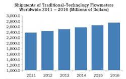
Despite the growth of new-technology flowmeters, such as Coriolis and ultrasonic, over the past few years, traditional technology flowmeters are holding their own. Many users are still selecting differential pressure (DP), turbine, positive displacement, and other more traditional meter types for their flow measurement applications. Traditional technology flowmeters share the following characteristics:
- As a group, these meters were introduced before the end of World War II.
- They are less the focus of new product development than new-technology meters.
- Their performance, including criteria such as accuracy, is not at the same level as the performance of new-technology flowmeters.
- They generally have higher maintenance requirements than new-technology flowmeters.
- They are slow to incorporate recent advances in communication protocols, such as HART, FOUNDATION Fieldbus, and Profibus.
Traditional-technology flowmeters include differential pressure, positive displacement, turbine, open channel, and variable area. Despite the inherent advantages of many new-technology meters, end-user demand for traditional meter types remains strong for a number of interesting reasons.
Differential-Pressure (DP) Transmitters
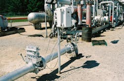
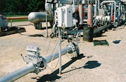
DP transmitters have been in use to measure flow for more than a century. DP transmitters rely on a constriction called a primary element in the flowstream to create a pressure drop in the line. They measure the difference between downstream and upstream pressure to compute flow, using Bernoulli’s theorem. DP transmitters rely on a variety of primary elements to create the constriction in the line.
DP transmitters are part of a family of pressure products. Other types of pressure transmitters include absolute and gauge. Absolute pressure transmitters measure pressure without taking atmospheric pressure into account. Gauge pressure transmitters include atmospheric pressure in their pressure measurement. Between the two, gauge pressure transmitters are more common than the absolute variety.
One of the most important developments in pressure transmitters with implications for flow has been the development of multivariable pressure transmitters. Multivariable transmitters measure two or more process variables. In the context of flow, they have differential-pressure capability, which allows them to compute volumetric flow. In addition to this measurement, they contain a pressure and temperature sensor and/or transmitter to make a temperature and/or pressure measurement. Multivariable pressure transmitters that measure differential pressure, temperature, and gauge or absolute pressure can compute mass flow. This makes them capable of measuring the mass flow of steam and gas.
Primary Elements
While there are many types of primary elements, orifice plates are the most common. Orifice plates consist of a usually round, usually metal (typically steel) plate with a hole or “orifice” in it. The purpose of the hole in the plate is to force fluid in a pipe to pass through it, thereby creating a pressure drop downstream of the plate. There are many types or orifice plates with different-shaped openings positioned at different locations on the plate. Some of the more common types include concentric, eccentric, and segmental.
Experiments with DP transmitters using orifice plates to measure gas flow took place in the late 1920s, culminating with the publication of AGA-1 in 1930. This was a report by the American Gas Association (AGA) that constituted the first “industry standard” for orifice plate meters. Further testing resulted in the publication of AGA-2 in 1935 and AGA-3 in 1955. These reports gave orifice plate meters a dramatic lead in installed base among flowmeters for custody-transfer applications. It wasn’t until 1981 that the AGA published a similar report for turbine meters, called AGA-7. In 1998, the AGA published AGA-9, a report on the use of ultrasonic flowmeters for custody transfer of natural gas.
Other types of primary elements include Venturi tubes, flow nozzles, Pitot tubes, wedge elements, and laminar flow elements. Of these types, Venturi tubes, flow nozzles, and Pitot tubes are the most common. Venturi tubes bend up at one end and are elongated at the other end. They are often used for large pipe applications, including water and wastewater. Flow nozzles are often used to measure steam flow. The most popular form of Pitot tubes are averaging Pitot tubes, and they are used to measure airflow and other forms of gas flow. They are also used to measure stack and exhaust gas emissions.
Positive Displacement
The history of positive-displacement (PD) flowmeters goes back to 1815, when Samuel Clegg invented the first PD gas meter. This first meter was a water sealed rotating drum meter. In 1843, Thomas Glover invented the first “dry” PD meter. Glover’s meter contained a sliding valve and two diaphragms. Today’s diaphragm meters are similar in design, but are made of cast aluminum with synthetic rubber-on-cloth diaphragms. Bopp & Reuther of Germany holds the first patent on oval gear meters, which it obtained in 1932.
One of the main uses today for PD meters is for gas utility billing applications. There are two main types of PD meters used for this purpose—diaphragm meters and rotary meters. Rotary meters are replacing diaphragm meters in many cases. Rotary meters are smaller and lighter than diaphragm meters. This replacement is occurring for other gas applications as well. Elster is the dominant supplier in this market.
Oval gear meters are quite popular for oil applications, especially for downstream oil distribution involving custody transfer. Here they compete with Coriolis meters, which are gaining market share in downstream oil measurement.
Positive-displacement meters do best in line sizes between 1.5 inches and 10 inches. It is unusual to find PD meters in line sizes above 10 inches. One strength of PD meters is high accuracy. Positive-displacement meters actually capture the fluid in compartments of known quantity and measure how often they do this. They are also very good at measuring fluid with low flowrates. Downsides of positive-displacement meters include pressure drop and mechanical moving parts.
Turbine
The first turbine flowmeter was invented by Reinhard Woltman in 1790. This makes turbine the earliest meter invented among the flowmeters used in the modern era. Turbine meters precede DP flowmeters by at least 100 years. Despite their early invention, it wasn’t until after World War II that they began making an impact on industrial markets. During World War II, they were used to measure fuel consumption on military aircraft. Soon after this period, they began to be used in the petroleum industry to measure the flow of hydrocarbons.
In 1953, turbine meters began to be used to measure gas flow. Rockwell introduced turbine meters to the gas industry in 1963. Within 10 years, they were widely used in the gas industry for measuring gas flow. In 1981, the American Gas Association published its Report #7, “Measurement of Fuel Gas by Turbine Meters.” Since that time, turbine meters have become firmly entrenched in the gas industry, especially for custody-transfer applications.
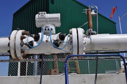
Turbine meters compete with ultrasonic and DP flowmeters for measuring custody transfer of natural gas. They are widely used for custody transfer of natural gas in large natural gas pipelines. Turbine meters remain a viable choice for measuring steady, medium- to high-speed flows. They are more complementary than competing with positive-displacement meters, since they do best in larger line sizes (above 10 inches). The drawbacks for turbine meters are that they have moving parts (mainly the rotors) and they cause pressure drop.
Open Channel
Open-channel flow occurs when liquid flows in a conduit or channel with a free surface. Rivers, streams, canals, and irrigation ditches provide examples of open-channel flow. What is slightly confusing about this terminology is that that the flow of liquids in partially filled pipes, when not under pressure, is also considered open-channel flow. For example, water flowing through a culvert running underneath a street is considered open-channel flow. Likewise, flows in sewers and tunnels are classified as open-channel flows, along with other closed channels that flow partly filled. Other examples of open-channel flow include flow in water treatment plants, storm and sanitary sewer systems, industrial waste applications, sewage treatment plants, and irrigation systems.
Use of Weirs and Flumes: A very common method of open-channel flow involves the use of a hydraulic structure such as a weir or flume. These hydraulic structures are called primary devices. A primary device is a restriction placed in an open channel that has a known depth-to-flow relationship. Once a weir or flume is installed, a measurement of the depth of the water is used to calculate flowrate. Charts are available that correlate various water depths with flowrates, taking into account different types and sizes of weirs and flumes.
Area Velocity: Flow can be measured without a hydraulic structure, such as a weir or flume. In the area velocity method, the mean velocity of the flow is calculated at a cross-section, and this value is multiplied by the flow area. Normally, this method requires that two measurements be made—one to determine mean velocity and another measurement to determine depth of flow. Flow rate Q is determined according to the continuity equation:
Q = V x A
The area velocity method is used when it is not practical to use a weir or flume, as well as for temporary flow measurements. Examples include influx and infiltration studies and sewer flow monitoring.
Variable Area
Most variable-area (VA) flowmeters consist of a tapered tube that contains a float. The upward force of the fluid is counterbalanced by the force of gravity. The point at which the float stays constant indicates the volumetric flowrate, which can often be read on a scale on the meter tube. VA meter tubes are made of metal, glass and plastic. Metal tubes are the most expensive type, while the plastic tubes are lower in cost. Metal tubes are used for high-pressure applications.
While most VA meters can be read manually, some also contain transmitters that generate an output signal that can be sent to a controller or recorder. While VA meters should not be selected when high accuracy is a requirement, they do very well when a visual indication of flow is sufficient. They are very effective at measuring low flowrates, and can also serve as flow/no-flow indicators. VA meters do not require electric power and can safely be used in flammable environments.
One important development for variable area flowmeters is the development of meters with a transmitter output. The HART protocol is available on some meters. This turns the VA meter into more than a visual indicator, and makes it possible to do control and recording. A class of VA meters called purgemeters have been developed to handle a variety of low-flow applications. Other areas of research include float design and materials of tube construction, especially metal.
Jesse Yoder, Ph.D., is president of Flow Research Inc. in Wakefield, Mass., a company he founded in 1998. He has 25 years of experience as an analyst and writer in process control. Dr. Yoder specializes in flowmeters and other field devices, including pressure and temperature products. Dr. Yoder can be reached at [email protected].
For more information on Flow Research’s Volume X: The World Market for Flowmeters, 4th Edition, visit www.floweverything.com.
About the Author
Jesse Yoder
Jesse Yoder, Ph.D., is president of Flow Research Inc. He has 30 years of experience as an analyst and writer in instrumentation. Yoder holds two U.S. patents on a dual-tube meter design and is the author of "The Tao of Measurement," published by ISA. He may be reached at [email protected]. Find more information on the latest study from Flow Research, "The World Market for Gas Flow Measurement, 4th Edition," at www.gasflows.com.


