Moving beyond basic temperature measurement instrumentation to improve performance and reduce costs
The installation for this discussion involves adding a process temperature measurement point to an 8-inch straight, horizontal section of Schedule 40 piping. The process fluid is water with an average flow of 750 gallons per minute at pressure of 75 pounds per square inch and temperature of 150ºF. Originally, in designing the process piping, it was anticipated that a temperature reading would be useful, and a 3-inch flanged process connection was installed on the pipe, which has been closed with a blank flange. The scope of the installation project calls for the following:
- Replace the blank flange with a suitable flanged thermowell to immerse the temperature sensor in the liquid stream while providing a terminal block for the electrical connections.
- Install a temperature sensor in the thermowell and secure the necessary terminations.
- Run appropriate extension wiring from the thermowell terminal block to the automation host system via existing cable trays and marshalling cabinets.
- Secure ultimate termination at the I/O card of the automation system.
On the surface, it is a simple project and should be easy to implement. The following examples illustrate the differences and advantages between two approaches.
Standard traditional approach
In a traditional approach, a hypothetical engineer would select a stock thermowell with a compatible mating connection and made from a suitable material. The insertion length should reach the center of the main pipe, so in this case, the insertion length should be half the inside diameter of the 8-inch pipe plus the additional length of the spud. Given the length, a straight-stem thermowell with an outside diameter of 1 inch would be about right for this insertion based on other similar installations in the plant.
For selection of a sensor, there are several possibilities suitable for the temperature range. In this example, the engineer would select a type K thermocouple (TC), since it is capable of handling anything the process is likely to experience. It can be connected to a home-run cable via the terminal block at the thermowell head (see Figure 1). During a process shutdown, plant personnel remove the blank flange and bolt the thermowell and sensor in place with a gasket. A reel of type K extension wire is sufficient to cover the 200 feet from the thermowell to the I/O rack of the host system via one marshalling cabinet.
While making the connections, the technicians maintain correct polarity while trying to place the cable in the trays as far as possible from any existing power lines to avoid electrical interference. Given the low voltage of the TC signal, all the terminations must be checked carefully.
At the I/O rack, the sensor extension cable ends at a temperature sensor card, which can be configured for a type K TC so that the host system can display the temperature measurement for the operators and it can be used in the larger control strategy.
The solution selected for this project is commonly used, but leaves much to be desired. So, what is wrong, or less than optimal, about this approach? The following considers an alternative.
Analysis using thermowell design software
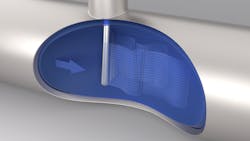
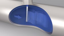
A more advanced approach to this project includes selecting individual measurement components to optimize performance and safety while reducing installation and future maintenance time.Thermowell selection requires careful analysis to avoid maintenance problems related to vortex-induced vibration (VIV) caused by wake shedding effects (see Figure 2) when a thermowell is inserted into a flowing liquid stream perpendicular to the flow direction. In situations where the VIV frequency matches the resonant frequency of the thermowell, the vibration can cause metal fatigue, resulting in a break and loss of containment.
To avoid this situation, many engineers will simply select an oversized straight-stem thermowell profile, such as in the previous example. This increases the internal pipe obstruction, slows response and may keep the sensor from reaching the full process temperature due to stem conduction errors.
Design analysis using software based on formulas outlined in the ASME PTC 19.3 TW-2016 standard can determine the viability for a given thermowell profile based on its physical strength and vibration characteristics at specific operating conditions. With effective software, it is a simple matter to work through what-if scenarios to ensure the thermowell selected will avoid VIV problems at a range of operating conditions including startup, product grade change, likely upsets and others, in addition to “normal” operation. Some plants have experienced thermowell failures when running under abnormal conditions even though analysis concluded the design was suited for normal conditions.
Undertaking this analysis using thermowell design software and then investing in a more optimized thermowell with dimensions suited to the specific process will improve temperature measurement performance and liquid flow for the life of the installation.
Selection of the specific sensor can be debated. Some engineers might prefer a resistance temperature detector (RTD) instead of a TC, but in a basic application such as this, either could work well. When evaluating the differences, RTDs are generally considered more accurate and stable than TCs but tend to be more physically delicate and more susceptible to vibration. TCs typically respond to changes more quickly and are more rugged than RTDs but can drift if their metallurgy changes due to prolonged exposure to high temperatures.
Many detailed resources are available on the RTD versus TC question, but a clear area for improvement is the use of direct wiring and the issues it presents. Either type of sensor requires dedicated cabling, which can be expensive and only works with the specific sensor type. If the plant decides to change from a Type K TC to an RTD or even a different TC type, the cabling will need to be replaced. Moreover, the automation system must have a dedicated temperature sensor input, which may not work when switching from an RTD to a TC or vice versa, or even from one type of RTD or TC to another.
Improving the measurement chain
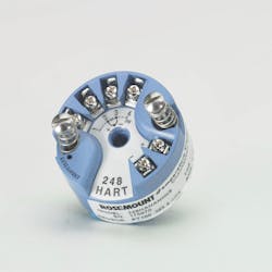
Adding a temperature transmitter (see Figure 3) at the thermowell terminal enclosure converts the weak voltage of a TC or small resistance of an RTD to a more robust 4-20 mA current signal. This signal amplification makes it much less susceptible to interference present in many plant environments. A current signal can be carried by standard instrument cabling and added to the automation host system via a standard 4-20 mA input card. Similarly, wireless or digital fieldbus protocols can be used if they are already deployed within the facility.
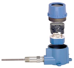
If a different type of sensor is required, it is a simple matter to reconfigure the transmitter. Sophisticated HART and fieldbus transmitters support remote configuration and diagnostic functions, which can call attention to developing problems and assist in troubleshooting.While transmitters have been in use for many years, developments in advanced diagnostics have been more recent. New features can identify changes to sensors indicating degradation before outright failure. While something basic like an open circuit or erratic transmission is easy to identify, advanced transmitters (see Figure 4) can use their capabilities to detect more subtle problems that can lead to serious issues such as on-scale errors.
For example, a transmitter designed to work with both TCs and RTDs must have built-in capabilities to read both voltage and resistance. If a TC is in use, it processes the signal by measuring voltage, but it still has a resistance circuit, so it can be programmed to take resistance measurements of the TC element at specific intervals. This can be done quickly to minimize any interference with a critical temperature measurement. This resistance check provides a snapshot of the condition of the TC and can be used to detect deterioration capable of causing problems with the temperature measurement.
When a temperature measurement is especially critical to a process, redundant sensors can be an option. This adds an online “hot” backup capability while operating, so the transmitter can switch seamlessly from a primary sensor to a backup sensor, reducing the chance of losing a temperature reading.
The hot backup capability can be employed with a single dual-element sensor or two independent sensors. Risk of losing a measurement is reduced with two independent sensors versus a single dual-element sensor; however, this requires additional process intrusions. Two independent sensors — even if they are wired to one transmitter — can reduce the probability of losing the reading by up to 80%, depending on the failure rate of the sensors. Two sensors measuring the same temperature can also be monitored for drift by comparing their values via a drift alert diagnostic. If the differential between the two readings exceeds a user-specified baseline, it can indicate one of the sensors is degraded and has begun to fail.
Advantages of advanced solutions
The initial instrumentation cost of the advanced solution can be higher than a more traditional approach; however, the advanced solution delivers critical operational cost savings and lower installation costs through the following advantages:
- Better temperature measurement performance can help support process optimization.
- Condition diagnostics reduce troubleshooting and maintenance costs.
- Sensor selection options provided by the transmitter eliminates the need to replace cabling if changing sensor type.
- Optimizing thermowell design using analysis software minimizes flow obstructions and pressure loss while extending equipment life.
- Eliminating higher-cost sensor wiring reduces installation cost.
While configuring advanced systems may require some additional effort and engineering time, the results — improved performance and reduced maintenance — are worth it.
Ryan Leino is a global temperature product manager for Emerson’s Automation Solutions business in Shakopee, Minnesota. He holds a Bachelor of Science in chemical engineering from University of Wisconsin, Madison.


