Pressure measurement, Part 2: Features, specifications and design considerations
The first article in this series on pressure measurement and field instrumentation, which appeared in the May/June 2022 issue of P.I. Process Instrumentation, discussed how pressure transmitters work. This installment focuses on the features and specifications of the transmitters themselves, using real-world examples to illustrate design considerations.
There are likely as many options and features of pressure measurement equipment as pressure measurement applications. Instrument manufacturers relentlessly upgrade field instrument software and hardware to meet the ever-increasing demands of complex industrial process facilities. This article focuses on the pressure measurement equipment used in these industrial facilities.
Instrumentation and controls technicians, energy managers and others rely on field instrumentation to accurately monitor and control crucial process variables. These process variables directly impact the quality of the end product, the throughput of the process and the safety of workers in the facility.
Industrial pressure measurement equipment runs the gamut, from the simple to the complex. Pressure gauges are simple devices that are read locally by an operator. Pressure switches turn blowers, pumps and other equipment on or off. Pressure transmitters are the most comprehensive pressure measurement instruments along this spectrum. Pressure transmitters are electromechanical devices comprised of sensors that measure pressure and transducers that convert that measurement into an electrical signal suitable for communication with a modern control system.
Industrial pressure transmitters
Industrial pressure transmitters are capable of measuring gas, steam and liquids under extreme conditions. In industrial facilities, it is commonplace for processes to be under high pressures and temperatures, in addition to aggressive media types such as highly corrosive or abrasive liquids.
The oil and gas, chemical and petrochemical, metals and mining, pulp and paper, and food and beverage industries use industrial pressure transmitters across various demanding applications. Saturated steam used for heating is ubiquitous throughout process facilities and is typically generated at high pressures and temperatures for distribution throughout a facility. Caustic and abrasive slurries such as white, green and black liquors are used in the kraft process in paper making.
These extreme conditions require appropriate design and use considerations to preserve product quality standards, maintain process uptime and ensure the safety of workers in these facilities. Modern industrial pressure transmitters have integrated alarm outputs that can aid process operators in process alarm management best practices. Many areas of industrial facilities are hazardous and require all electrical equipment to be rated as explosion-proof or non-incendive/intrinsically safe.
Basic transmitter construction
The design and selection of pressure transmitter materials are primarily based on required performance specifications and process conditions. Measurement accuracy and rangeability are typically out-front regarding performance specifications. Process media temperature, corrosivity, abrasiveness and pressures are essential considerations of the process conditions. And, of course, the static and differential pressures the instrument may be expected to withstand are significant considerations for pressure measuring instruments.
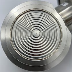
Every manufacturer has basic geometric and material standards for transmitter design, but perhaps the most critical consideration is where the process media contacts the instrument: the barrier diaphragm. The thickness, diameter, material and even location of the barrier diaphragm relative to the sensitive electronics dictate how much pressure and temperature the instrument can handle and how sensitive it is to small fluctuations in process conditions.
Smart transmitters
Many industrial transmitters are described as being “smart.” Generally speaking, this means the instrument has onboard memory, uses a microprocessor to perform calculations and run diagnostics, and can communicate via digital communication protocols such as HART or Modbus.
Additionally, operators can send information to smart instruments via software or handheld communicators to remotely configure and calibrate the instrument. Even the most sophisticated field instruments have sensors that drift over time, and regulatory bodies may require calibration services at regular intervals. This ease of communication with microprocessor-based smart instruments translates to cost and time savings for process facilities.
Power and input/output signals
Some field instruments do not always need electrical power to operate. An operator can read a gauge locally, and a switch may open or close based on some pressure set point, with no electricity required. Other instruments, such as large electromagnetic flowmeters, generate electromagnetic fields and have back-lit displays. These features require a relatively high amount of energy to operate. Therefore, they need a dedicated power cable and a separate signal cable for communications.
Most industrial pressure transmitters, however, do not require much electricity to operate and can run on “loop power.” In a loop-powered device, the energy needed to power the device is supplied via the same wires that carry the communication signal. Since a single set of wires is used instead of two, loop-powered devices provide significant labor cost savings. The cost savings are even more effective if the field instruments are installed far from the control system.
Communicating with a controller
If a controller can be thought of as the “brain” of a process, field instruments are nerve endings at the end of the fingertips. They gather process information (pressure, temperature, flow) at the point of contact and communicate it back to the controller. These communications can happen through a variety of means.
Analog communications
Many devices communicate with process controllers via an analog signal. Analog signals are typically in the form of a voltage or current signal. A 4-20mA (milliamp) signal is by far the most common form in industrial facilities. Pressure transmitters typically output an analog signal that is directly proportional to the pressure being measured.
Digital communications
Most smart transmitters can also interface with controllers via digital communication protocols, such as HART, Modbus, DE, Profibus or other standards. Some of these standards are open, and some are proprietary to a specific vendor. But they all allow for a large amount of data transfer at a rapid rate. Technicians can utilize digital communications via connected central control systems, laptop computers or tablets with special software and modems, or handheld communicators (e.g., HART communicators).
Data communications protocols are sets of rules that allow two or more devices in a system to transmit data or communicate with each other.
- DE — The DE, or Digital Enhanced protocol, was initially developed in the 1980s as a proprietary communications protocol for industrial applications. It has largely been replaced by industry-specific protocols over time, especially HART. However, many long-running industrial facilities (oil and gas refiners, pulp and paper mills, and others) do still use DE communications*.
- HART — HART (Highway Addressable Remote Transducer) protocol is an open standard for sending and receiving digital information using analog wiring. HART signals share the pair of wires used by analog signals. In effect, additional digital data is transferred without additional wiring, making HART a popular choice to implement over legacy systems.
- Modbus — Modbus is an open protocol that has become a de facto standard used to connect industrial electronic devices. Modbus is relatively easy to deploy and places few restrictions on the format of the data to be transmitted.
*Some devices are “bi-lingual” and can communicate via both DE and HART protocols.
Common design considerations
Most pressure instrumentation manufacturers offer many design options depending on the end user's preferences and requirements. The most common design options are explored below.
Process connections — The meter body covers, where the impulse lines run from the process to the transmitter, typically have threaded connections. In the United States, 1/2" NPT and 1/4" NPT internal threadforms are most common, although other threadform standards are available. Adapters (sometimes called footballs due to their shape) can provide installation flexibility. For example, to connect a transmitter with a 1/4" NPT thread to a process that has 1/2" NPT existing threads.
Electrical connections — 1/2" NPT watertight electrical connections are standard in North America. Power and signal cables run through these electrical connections and should be secured with cable glands.
Impulse line mount vs. direct mount — Pressure transmitters can be connected to the process via tubes or pipes (sometimes called impulse lines) or mounted directly to the process.
- Impulse line mount: Tubes or pipes connect the high-pressure side of the transmitter to the high-pressure point to be measured and the low-pressure side to the low-pressure point to be measured.
- Direct mount: Gauge pressure transmitters are mounted directly onto a tank or pressurized vessel. The diaphragm contacts the process media directly without needing impulse lines. There are no adapter flanges, and the meter body structure itself is smaller.
Visible display and orientation — Many transmitters have local displays in the electronics housing, allowing operators to read the pressure locally at the point of installation. Most manufacturers offer transmitters with rotating displays and electronics housing. Before installation, the display and electronics housing should be orientated to make viewing the display easy for operators.
Materials — Most manufacturers offer a variety of material options for components that will contact the process (wetted) and components that will contact the surrounding environment only (non-wetted).
- Centerbody wetted materials (barrier diaphragms, meter body covers, process flanges) — Stainless steel is the most common wetted material. Stainless steel is durable, chemically compatible with most process media and relatively inexpensive. Other wetted materials such as Hastelloy or tantalum are commonly used for more corrosive or abrasive applications.
- Nuts/bolts — Depending on the environment and anticipated working pressures, various grades of stainless and carbon steel nuts and bolts are available. It is important to note that the working pressure of a transmitter may be affected by nut/bolt materials. The transmitter assembly is only as strong as its weakest component. A transmitter's pressure rating can be downgraded if nut/bolt materials other than specified are used.
- Coatings/paints — Pressure transmitters typically have a standard baked acrylic paint on the aluminum electronics housing, which protects against corrosion in most environments. For highly corrosive environments, corrosion-proof urethane coatings should be used.
Local configuration/control — Some manufacturers offer local configuration options. Common local configuration options are zero and span adjustments and changing units of measure. Local configurations can typically be made with push buttons, touch displays or a magnetic stylus.
Special considerations
There are too many transmitter design options to list without becoming overwhelming. Special fill fluids, cleaning procedures for oxygen or chlorine service, custom calibrations and test reports, and various certifications are available to suit application requirements.
Optional hardware like mounting brackets, manifolds, drain plugs, special flanges and remote seals are available directly from the manufacturer or third parties. These options expand capabilities through ease of installation and use, protecting the instrument from heat, corrosion or abrasion and even allowing an instrument to be taken out of service without disrupting the process.
Hopefully, this article has helped explain modern industrial pressure transmitter design and functionality in a practical and interesting way. In the next two installments in this series, we will explore how pressure measurement equipment can be used for level and flow measurements.
Ryan Bennett is a product marketing manager for Azbil North America, based in Denver, Colorado. He holds a B.S. in Industrial Distribution from the University of Alabama at Birmingham. Ryan has worked in various roles at Azbil North America, with a current focus on product management and marketing. He can be reached at [email protected].
About the Author

Ryan Bennett
Product marketing manager
Ryan Bennett is a product marketing manager for VorTek Instruments in Longmont, Colorado. He holds a B.S. in industrial distribution from the University of Alabama at Birmingham. Bennett has had a strong focus on steam metering, control and distribution throughout his career. He has worked in various roles at VorTek Instruments, with a current focus on new product development and marketing. Bennett can be reached at [email protected].


