Understanding and solving control valve cavitation problems
You are standing near a recirculation valve on a high-pressure boiler feedwater pump. You notice the pipe and valve shaking violently, and it sounds like rocks are passing through the valve, but you know the line contains clean water. What is going on?
It is cavitation — a liquid flow phenomenon that can occur in control valves, pumps, boat propellers, pipes and any situation where liquids are moving across a huge pressure differential. Before discussing the issues caused by cavitation and the ways to address them, it is important to understand exactly what cavitation is and why it occurs.
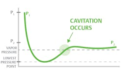
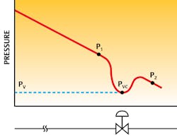
Figure 1 shows the instantaneous pressure as liquid moves through a control valve. The internal passages of a valve vary in a cross-sectional area, and the inlet and outlet areas are generally much larger than the area around the plug and seat. Since the total flow at any location in the valve is the same, the liquid velocity around the plug and seat must be much higher to pass the same flow.
By Bernoulli’s law, the total energy at every point is constant, so if velocity is increased, pressure must fall. This explains the pronounced dip in the pressure curve. As the fluid passes through the restriction, it must speed up, lowering the pressure at that point. Vena contracta is the minimum area of a flow stream, and it is located downstream of the flow constriction. This is the point in flow where the average flow velocity is the highest, and mean pressure is the lowest. Once the liquid enters the much larger outlet piping, it slows down, and some pressure is recovered.
If the instantaneous pressure in the vena contracta falls below the vapor pressure, then vapor bubbles will begin to form. However, when the pressure recovers above the vapor pressure downstream of the vena contracta, as shown in Figure 1, the bubbles (or vapor cavities) will immediately collapse back into the liquid. This formation and collapse of the bubbles is called cavitation. If the outlet pressure is less than the vapor pressure of the liquid, these vapor cavities will persist downstream of the valve. This is called flashing.
How dangerous can a bubble be?
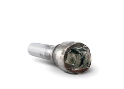
While either flashing or cavitation can cause severe damage to a control valve, this article will focus on the effects of cavitation. It may be surprising, but most of the damage associated with cavitation does not occur when the bubbles are formed, but rather when the bubbles collapse and disappear (see Figure 2).
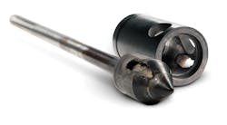
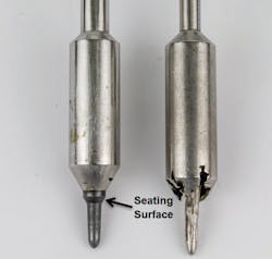
Initially, the bubble is spherical, but a collapsing bubble usually develops a dimple, which ultimately penetrates the bubble as it condenses back to liquid. The implosion of bubbles creates high-speed, destructive microjets and localized shock waves. Either of these phenomena, when located near the material surface, can cause severe damage to valve elements such as the plug, seat, body and associated pipe (see Figure 3). Cavitation will not only erode the internals of the valve, but it will also hasten chemical attack if the fluid is corrosive.
Cavitation might also limit valve flow capacity. As the level of cavitation rises, the amount of vapor in the valve outlet begins to restrict flow. At some point, the downstream vapor load will become so high that the flow becomes choked. For a set inlet pressure and fixed valve position, a valve under choked flow conditions cannot pass more liquid, regardless of how low the downstream pressure is reduced.
Detecting and/or predicting cavitation
It is quite difficult to predict the onset of incipient cavitation, but there are some methods to predict and detect the severity of cavitation. The first method is the obvious noise and vibration created by a severely cavitating liquid. The valve and downstream piping will sound like it has gravel flowing through it and will usually be vibrating significantly. A standard valve in this service will not last long. The rough, irregular and cinder-like pitted damage of the valve internals (as shown in Figure 3) is also a sign of severe cavitation in an application.Predicting the severity of cavitation during the design phase is preferable to detecting it after installation. ISA’s Recommended Practice 75.23 (Considerations for Evaluating Control Valve Cavitation) defines a cavitation index (σ) for an application, which is a ratio between (P1-Pv) to (P1-P2). Depending on the value of σ, the severity of cavitation can vary from incipient cavitation to severe vibration, choking and material damage.
The cavitation index does not convey any information about the performance of a particular valve in an application. Different valves can tolerate varying levels of cavitation, and each application may be focused on a different aspect of cavitation — for instance, noise versus vibration versus damage.
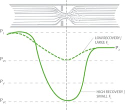
Valve manufacturers establish limits for their designs based on experience with the application and the specific design features of their products. Cavitation might be more pronounced on high recovery valves such as butterfly, ball and plug valves. High recovery valves typically have a lower vena contracta pressure (see Figure 4), thereby increasing the chances of bubble formation and cavitation.
The key process parameters required to evaluate cavitation damage potential are upstream and downstream pressures, fluid temperature, and the vapor pressure of the liquid. Vapor pressure is usually easy to obtain for a pure fluid (water, ammonia, methanol, etc.), but can be quite difficult to determine for combinations of fluids, hydrocarbon mixtures or poorly studied intermediate compounds. An accurate estimation of vapor pressure is critical to evaluate the intensity of cavitation.
Cavitation is much more likely if a valve is taking a very high pressure drop or the liquid temperature is elevated, translating to a high vapor pressure. The boiler feedwater pump recirculation valve (described at the beginning of this article) had both of these conditions.
Cavitation damage potential is a function of the duty cycle of the cavitating conditions. If the valve will experience the cavitating condition only during a rare upset, this condition may not jeopardize the overall performance of the valve since the damage effects are time-dependent. Also, cavitation issues generally scale with flow rates. A larger flow rate means more fluid is available to cavitate, and there is a greater potential for damage.
Cavitation solution #1: Avoidance
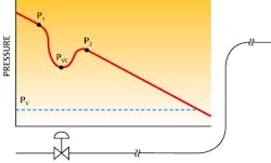
The best way to handle cavitation is to avoid it altogether. Cavitation occurs when the outlet pressure of the valve is fairly close to the vapor pressure of a liquid. Consider the valve shown in Figure 5. As the fluid moves down the pipe, the pressure gradually falls due to line losses. If the valve happens to be installed in a location where the liquid is approaching its vapor pressure, the likelihood of cavitation in the control valve is high.
Now consider Figure 6. In this case, the valve has been moved to a different location where the pressure is higher. Perhaps the valve is closer to the pump, so the line losses are reduced, or the valve is located in a section of pipe where the head pressure is higher. In either case, the valve outlet pressure is well above the vapor pressure, and cavitation is less likely.
If valve placement is not flexible, flow resistance can be added downstream of the control valve utilizing an orifice plate or a valve. Fluid pressures within the valve increase, and it will experience less pressure drop. However, this technique may simply displace cavitation from the valve to the downstream restriction and may not effectively control the cavitation in the system. This may also increase valve size, as less pressure drop is available to pass the same amount of flow. Other means of avoiding cavitation might include shaving a pump impeller or installing a variable frequency drive on a pump to reduce the pressure drop across a valve.
Cavitation solution #2: Design for it
If cavitation cannot be avoided, then the valve must be designed to handle it and minimize the damage. There are three ways to accomplish this:
- Robustness
- Isolation
- Elimination
Often, a combination of two or even all three techniques is employed in valve design.
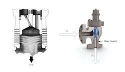
Isolation attempts to divert or direct the collapsing bubbles into the middle of the flow stream where microjets and shock waves cannot impinge on valve components. There are many techniques to accomplish this, including the two valve designs shown in Figure 8.
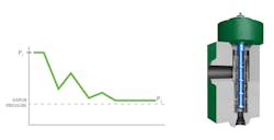
Elimination strives to minimize cavitation by taking the pressure drop in a series of stages rather than all at once. A single pressure drop tends to have a large dip (as shown in Figure 1), which drops below the vapor pressure of the liquid. If the pressure drop is taken in a series of three or four stages, the pressure dip is eliminated, and the pressure remains above the vapor pressure (see Figure 9).
Conclusion
Cavitation can occur whenever a valve takes a very high pressure drop or when a liquid is near its vapor pressure. If unanticipated, cavitation can quickly destroy valve internals and even erode through pipe walls. However, calculations are available to anticipate cavitation problems in advance. Armed with that knowledge, designers can either rework the equipment design to eliminate or mitigate cavitation, or they can partner with a control valve vendor to select the best valve design to handle the challenging process conditions.Thirumalai Karthik (TK) Arasu is a critical control valve specialist with Emerson. He has 13 years of application experience specializing in anti-cavitation, anti-noise and high-performance engineered control valves.
