It is common for a pressure sensor to perform well at first and then later fall outside of the acceptable range of performance. Frequently such errors are classified as drift, when in reality there are other forces at play. This article reviews the influence of barometric pressure, installation and drift on sensor performance.
Barometric Pressure
Barometric pressure change has a specific impact on sealed pressure sensors; this includes absolute and sealed pressure types of pressure sensors. It will not have any influence on vented pressure types such as gauge, compound gauge and vacuum pressure measurement.
The impact of barometric pressure is inversely proportional to the pressure range of the sensor. The larger the pressure range the smaller the effect barometric pressure changes will have on the sensor output. On lower ranges it can have a substantial influence on the sensor output.
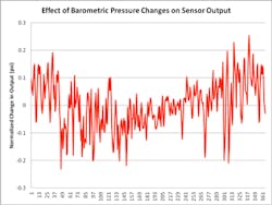
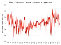
Graph 1 shows the effect of barometric pressure on sensor output for a 15-PSI range sensor each day over a period of one year. The graph shows the change in output normalized against the average shift in output. As can be seen, the shift in performance is somewhat seasonally cyclical but can vary significantly from day to day. The magnitude of the changes widely varies but tends to move within a certain range.
The effect will also be influenced by weather patterns of the area where they are used. This means that while Graph 1 swings from 0.25 to -0.23 PSI, it is not necessarily representative of the effect it will have in all areas and does not indicate a maximum range of change on the sensor output.
The variation and unpredictable nature of barometric changes can make it very frustrating to professionals attempting to keep equipment in calibration. I once spoke with just such an upset individual who indicated he had to recalibrate the sensors at least once a week and sometimes every couple days. After researching the issue, I determined that he was attempting to calibrate against barometric pressure changes and fighting a losing battle.
If changes in barometric pressure are resulting in inaccurate pressure measurement then the application should be examined to determine if a vented sensor could be used or if the pressure range could be increased without impairing the required output resolution. Other than different pressure type options that are offered at the time of purchase, this is a problem that the sensor manufacturer cannot fix and returning such sensors to a manufacturer for replacements will not correct the root problem.
Another potential solution is differential-pressure measurement. In essence this approach uses two sensing surfaces, where one is for process measurement and the other becomes the reference. Measurements are recorded as the difference between the two readings resulting in an output that is normalized to barometric pressure. Sensors exist that offer both in one unit, or it can be accomplished with two separate sensors.
Installation Shift
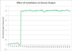
Graph 2 shows how a representation of the installation shift would look over a one-year period. Notice that other than the shift itself, the sensor output remained fairly constant. The graph is based on the installation shift of a 15-PSI range sensor. Installation shift also diminishes as the pressure range increases.
Output shift due to installation is usually a one-time shift. However, if the sensor is uninstalled for some reason (i.e. cleaning, relocating equipment) then it stands to reason that this shift will be realized again. It should be understood that the installation shift in output is not always the same magnitude each time that the sensor is installed.
The magnitude of the shift is affected by sensing method or technology used. Sensing elements that are fixed directly to the sensor diaphragm (or sometimes called the wetted surface) will be more susceptible to installation shift. Sensors where the sensing elements have been decoupled or separated from the sensor diaphragm are fairly isolated from installation effects on output.
What happens is that torque forces imposed on the sensor mounting threads during installation are being transferred to some degree to the sensor diaphragm. The effect of the torque forces on the sensor diaphragm usually varies from sensor to sensor and for each installation. As the torque forces vary with each installation so does the magnitude of output shift.
The variation in the magnitude of the output on a particular sensor can be controlled by using a torque wrench during installation. Set the torque wrench to the sensor manufacturers recommended installation or mounting torque and use it at the same setting each time.
The most common method for managing installation shifts is to adjust or calibrate the output after installation. This can be done with the actual sensor if the sensor has been designed with a “zero” adjustment that can be adjusted in the field. If not, then it can be managed by programming an offset into the sensor controller. Generally speaking, installation effect is best handled at the end-user level.
Drift
Piezo-resistive pressure measurement drifts over time and all sensors will exhibit this behavior. The magnitude or rate of change on the sensor output from drift is what is of concern, as the faster the rate of drift the sooner the sensor will drift out of specification. Ideally it will take years for this to happen.
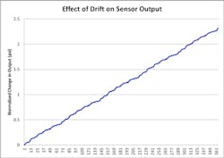
True drift is characterized as continual drifting of the output over time in the same direction. Graph 3 shows a sensor drifting over a 365-day period on a 15-PSI sensor.
While the change in output will be different for every sensor Graph 3 clearly shows a trend of increasing output. This is characteristic of drift behavior. The ups and downs on the graph are caused by other sources. What you are looking for is a trend for the output to move in the same direction, positive or negative, over time.
Unlike barometric or installation effects on output, drift is not related to the pressure range of the sensor. This is the reason that all these effects are often clumped together and called drift. If a high-pressure-ranged sensor is having output changes it is almost always drift related.
The root cause of drift in sensors is fundamentally a design level issue with some caveats that are reviewed below. The sensor-bonding layer—the attachment method between the sensing elements and the sensor diaphragm or sensor fitting—is the cause.
The bonding layer requires curing for the sensor output to become stable. This curing should happen at the factory when the sensor is produced. Think of it like a cheese or fine wine that requires aging in order to achieve the expected characteristics and level of quality. The more the bonding layer has aged with use the more stable the output will be.
Aging requires rigorously exercising the sensor throughout the pressure range and over temperature. This of course continues to happen out in the field. The older sensors become without sustaining damage the more stable they typically become with reference to drift rate.
The challenge comes when the bonding layer has become disturbed by sustaining a sharp and/or jarring impact—for example, when the sensor is dropped with some force onto a hard surface or a pointed object is pressed against the sensor diaphragm. This causes fractures and stresses within the bonding layer.
The effect is to reset the aging that has already occurred and will cause it to drift until the bonding layer comes again to rest with additional aging. To accelerate the aging process requires cycling the pressure and temperature over time. This is why great care should be taken to ensure the sensors are not abused and to avoid objects entering the pressure port that are not designed to be there.
It used to be commonplace among users “in the know” to tap a pointed object such as a pen or pencil against different parts of the sensor diaphragm to adjust the sensor output. Tapping in the center would shift the output up and tapping on the side would bring it down. What has been discovered is that while this works to adjust the sensor output, it also disturbs the bonding layer and causes the sensor output to begin drifting—the output might be where the users wants it, but it will not stay there.
If the output has not drifted to the point that it is no longer possible to calibrate it, then it may be possible to fix the sensor without having to return it to the manufacturer by cycling temperature and pressure to simulate the aging process. Of these two influences, temperature has the greatest influence on aging on sensors in the field. This is not necessarily true during the production process, but once the diaphragm has been well exercised then temperature cycling takes the dominant role in aging.
The user can cycle the temperature as close to possible within the operating temperature range of the sensor, being certain not to exceed the range as doing so could result in additional damage to the sensor. Users can cycle from room temperature to the maximum rating of the sensor, allowing it to set or soak for a while at the temperature extremes. After aging the sensor should settle; if it doesn’t then the sensor should be returned to the manufacturer.
Troubleshooting
Characterizing the nature of the change can identify the reason for change in sensor performance. Knowing what type of influence is imposed on the sensor enables the operator to narrow down the root cause and develop a solution to the problem. Following is a process to accomplish this.
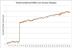
Graph 4 shows the total combined effect of the previous graph on the output. Installation shift is the easiest to identify and the most simple to fix. Most always it has already been compensated or adjusted for after installation. Graphically this can be done by subtracting the magnitude of the installation shift from all subsequent sensor readings. If the performance is otherwise fairly level then that was the problem.
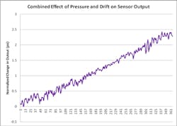
Graph 5 shows the combined effect of barometric pressure and drift on sensor output when the installation shift has been removed. In this example the problem is obviously more than just an installation shift. The next thing to do is to adjust for barometric pressure changes. Most weather websites have historical barometric data on file and available for downloading. By accessing these it is possible to normalize the measurements against barometric pressure variations. Doing so would, in this case, produce the graph shown in Graph 3.
Unfortunately in many cases long-term data is unavailable to analyze to determine the root cause of the problem. In these cases the problem is usually either identified by an operator frustrated by the need for frequent calibration or the output has shifted so much that the sensor can no longer be calibrated into an acceptable range.
In the case of frustration caused by frequent calibrations, if each time that calibration is performed the operator notes in which direction the output needed adjustment, it would only take a few calibrations (I recommend no less than three but more is better) before a determination could be made.
If the adjustment always had to be made in the same direction it is probably drift; but if the direction changes then it is either the result of barometric pressure changes or installation shift. Installation shift can be ruled out by always taking the measurement before uninstalling the sensor and calibrating it after it is installed. If the problem is still manifest after doing this then it is a drift problem; if not then the problem is an installation shift issue.
In instances when the sensor output can no longer be calibrated, the problem is either drift or damage to the sensor. In this case the best alternative is to return it to the supplier if it is within warranty and discard it if it is not.
Elden Tolman is Product Development Engineer at Automation Products Group (APG). Following a Bachelor of Science degree in Engineering from Utah State University, Mr. Tolman has worked at APG for nine years. In addition to developing products for several industries, most predominantly in Oil & Gas, he has an integral role in the design and testing of sensors to ensure EMI compliance. He writes regularly for the APG blog at www.apgsensors.com/about-us/blog and can be reached at 435 753-7300.
