Do your thermowells meet the ASME standard?
Thermowells are universally used in power, chemical, hydrocarbon and other industries. In 2010, the only U.S. standard assessing the design strength of thermowells was significantly changed for the first time in 35 years.
Thermowell fundamentals
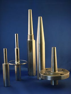
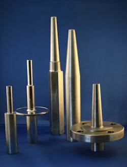
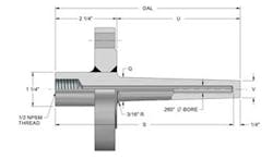
What could be simpler than a thermowell? Thermowells are metal products machined and gun-drilled from solid bar stock to encase a temperature sensor, such as a thermocouple or RTD. They are typically welded into place or attached to a process by means of a flanged or threaded connection. There are three primary thermowell shank styles. Conveniently, each of these is rather straightforwardly titled: straight, tapered and stepped. The core function of a thermowell is to enable the removal and replacement of a temperature sensor without opening up the process.
READ ALSO: Solving Erosion-Related Thermowell Failures
Designing a thermowell seems simple. The thermowell just needs to protrude far enough into the process fluid flow to allow the temperature sensor to reach the temperature of the process in a reasonable amount of time. Why not simply design the well to reach the middle one-third of the pipe and call it a day?
In many cases the middle one-third of the pipe may be a perfectly good rule of thumb. However, depending on process conditions there are a number of other factors that can cause a thermowell to suffer mechanical failure at insertion lengths less than one-third of the pipe. These include flow-induced vibration (wake frequency failure), dynamic (oscillating) and steady state stress, pressure, corrosion, erosion, material selection, and improper installation technique. All of these must be considered in properly designing a thermowell for a given installation.
So who is responsible for making the judgment call here? The 19.3TW standard makes plain that ultimate design responsibility for a thermowell well rests with the engineer designing the system into which the well is being installed:
Specification of a thermowell, including details of its intended installation and all intended operating conditions, is the responsibility of the designer of the system that incorporates the thermowell. The designer of that system is also responsible for ensuring the thermowell is compatible with the process fluid and with the design of the thermowell installation in the system.
This is primarily due to the fact that only the system designer has all the knowledge and details about the process conditions and installation arrangement required for the thermowell design. The thermowell supplier only knows what the system designer tells him.
What could be simpler than a thermowell? The devil, as they say, is in the details.
What is a thermowell for purposes of the ASME 19.3TW Standard?
Before plunging into the details of thermowell design it is important to have a good grasp of the fundamentals. Here is an easy question: What is a thermowell?
Remember the old saying: if it looks like a duck, walks like a duck and quacks like a duck, it is a duck? Thermowells are not ducks. There are many instances where something may look like a thermowell without falling within the design criteria for the 19.3TW Thermowells standard.
For example, the relatively subtle distinction between protection tubes and thermowells is an important one. There are no welds in a thermowell, except for a weld necessary to attach a flange to the thermowell shank. By contrast, protection tubes are commonly manufactured from metal pipe with a tip welded onto the end. Protection tubes are also commonly used in power, chemical, hydrocarbon and other industrial temperature measurement applications, often in low-velocity gas applications. Sometimes protection tubes are even casually referred to as "wells," but their design falls squarely outside the type covered under the scope of the 19.3TW standard. They are welded and there is no weld in a thermowell.
The 19.3TW standard modernized thermowell evaluation considerably by adopting modern bore sizes and shank constructions. However, there are a number of common thermowell designs that are outside the scope of the standard. For example, thermowells outside the scope include those that are shot-peened, coated, sleeve, or flame sprayed. Thermowells with velocity collars, external support or welds at any point other than a flange attachment are also excluded. Finally, even plain old solid bar stock thermowells can be outside the scope of the standard if they do not meet specific dimensional criteria. This does not mean that any of these arrangements is necessarily bad. It simply means that their design is outside the scope of the standard. Hence, any calculation results from 19.3TW may not be valid. In other words, the calculation results will not assure that the nonconforming thermowell can withstand the damage effects 19.3TW seeks to guard against.
History prompting the change from the ASME 19.3 to 19.3TW-2010 method
So how did we end up with a thermowell standard in the first place?
The intent of the original drafters of the 19.3 standard in 1974 was to create requirements for Power Test Code applications to prevent steam turbine-damaging thermowell failures in steam lines. The resulting document established a simple four-page calculation yielding a pass-fail result for steam line thermowells.1 The location of the requirements was somewhat unique since they were included in a code for testing rather than a code for design (such as Boiler and Pressure Vessel Code or Power Piping).
Due to the standard’s unique status and simple approach, over the years 19.3 was commonly used outside its original intended scope across a broad range of applications and industries. This was unintentionally enabled in part by limitations and ambiguities contained in the standard itself.
Despite broad implementation by engineering firms, field failures of thermowells cropped up and persisted on an intermittent basis in non-steam applications even among thermowells assessed by and built to the 19.3 standard. Among many noted thermowell failures, perhaps the most famous involved a sodium line at the Japanese MONJU nuclear reactor where a catastrophic thermowell failure resulted in a liquid sodium line leak.
Prior to the MONJU failure, engineering2 and academic3 criticisms of the old standard pointed out, among other concerns, that the ASME PTC 19.3:
- Failed to address in-line vibration
- Failed to assess oscillatory stress independent of steady state bending stresses
- Provided no fatigue factor for oscillatory stress or stress intensification factor for fatigue at the thermowell root
- Performed the installed natural frequency calculation in a crude manner without including any effects of foundation stiffness, fluid or sensor mass
Some publications4 and even standards5 actually referenced the 19.3 standard and then, not trusting its result, handicapped it. The opportunity for improvement was clearly identified.6 After approximately five years of work, in July 2010, the ASME PTC 19.3TW (2010) standard was published and received ANSI approval.
What changed in 19.3TW & why it is so much more conservative than 19.3
In most applications, 19.3TW is significantly more conservative than its predecessor, resulting in maximum allowable thermowell immersion lengths much shorter than previously allowed under the old 19.3 regime. This consideration is primarily due to consideration of in-line resonance and oscillating (dynamic) stress. In a small minority of cases primarily involving low-density gases where viscosity values are available 19.3TW may actually permit longer immersion lengths due to its ability to tailor the Strouhal number to a particular application, instead of relying upon a default value.
Other changes include accommodating modern geometries, step-shanks, an unlimited velocity range, a predicted life cycle, rules regarding manufacturing tolerances, dimensional limitations and consideration of corrosion and erosion factors. For the first time, 19.3TW made clear that support structures such as velocity support collars are ill-advised and outside the scope of the standard,7 primarily due to impracticalities regarding their manufacturing and installation. For the first time 19.3TW recognized that all thermowells are not equal in terms of their rigidity and susceptibility to vibration. Values such as the sensor mass, fluid mass and process connection design are for the first time incorporated into the calculation of the installed natural frequency of the thermowell.
However, for all of the modifications to the form and substance of 19.3 in 19.3TW, by far the most significant factor impacting thermowell design is the recognition of the need to avoid in-line resonance in most cases—the factor identified as the root cause of the MONJU failure.
Both in-line and transverse resonance are forms of wake frequency resonance. As process fluid passes a thermowell shank vortices are created in its wake and the thermowell stem vibrates.
When the thermowell vibration approaches the frequency of the shed vortices, the amplitude of vibration increases dramatically. This exerts tremendous force and stress against the thermowell”s base. In many cases this stress is fully capable of causing the thermowell material to fracture or even shear off at the point of greatest stress, the thermowell root.
The 19.3 standard conceived of thermowell vibration as occurring in a single plane transverse to the flow. Resonance was judged as possible whenever the wake frequency approached 80 percent of the natural frequency of the installed well. Indeed, transverse vibration is a real danger and its occurrence should be avoided if possible as it can be catastrophic for the well. However, a thermowell does not vibrate in a single plane. In reality the thermowell vibrates in an oscillating fashion that includes an in-line component. The in-line component can begin to resonate with the shed vortices at wake frequencies spanning 40 percent to 60 percent of the installed natural frequency of the well.
Recognition and avoidance of dangers posed by in-line resonance is critical to proper thermowell design, but the practical effect of reducing the wake to natural frequency limit from 0.8 to 0.4 can be very significant. The danger of thermowell resonance must be considered at velocities much lower than previously considered problematic by 19.3.
Since process fluid speeds will not slow to accommodate the ideal length of a thermowell, the effect is a reduction in the maximum allowable unsupported lengths for many thermowells. This reduction challenges engineers involved in design of thermowell applications to update their standards to reflect appropriate immersion lengths based upon a more conservative mechanical standard or to bulk up their thermowells to enable a sufficient immersion length. As a result, engineers applying the 19.3TW standard can now be more confident in their thermowell installation integrity. For every give, however, there is a take and the complexity of the calculation required to assess thermowell designs has greatly increased.
Supplier-generated thermowell design software applying the 19.3TW standard such as SwiftyCalc is helpful, but like everything else in order to reap a full benefit it is helpful to have a fundamental understanding of how and why the standard works the way that it does. The 19.3TW standard provides two example calculations that can be used to validate the software results.
But does the 19.3TW really work? The proof of the pudding is in the tasting
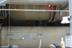
So here is a quick tale of two wells in a common trap for the thermowell designer prior to the publication of 19.3. The setting is a large circulating water line with thermowells installed on the outside elbow of the pipe. Thermowells are designed based upon traditionally successful engineering in-house standard and installed on the outside of the water line following an elbow.
A month following the installation the gauge installed in the well is found to be leaking water by operators. The well is removed and is discovered to have failed. Because the shank of the well is missing entirely, the operators at first suspect that a ceramic well has been provided by accident.
A root cause analysis is performed and wake frequency calculations per the original 19.3 requirements are performed providing velocity values calculated from the maximum flowing condition, based on pump run-out. The thermowell passes muster under the calculation. Because the investigating engineer is on the 19.3TW committee, the then-unpublished 19.3TW calculation is applied to the incident. The well also passes muster under 19.3TW. The thermowell design itself is examined and it is found that the manufacturer supplied an "off-the-shelf" thermowell instead of the specified design. An order is issued for a replacement well. Proper manufacture is confirmed and the well is re-installed. A few weeks later the operators call back. The well has failed again!
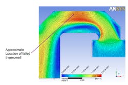
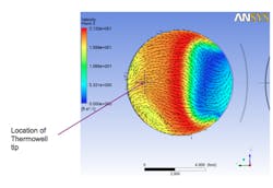
This time the velocity value is questioned and a computational fluid dynamic (CFD) model is performed. The model shows that actual velocity at the well location is approximately twice what had been designed for based on pump run out.
The CFD model demonstrated how the fluid flow stratified significantly along the backside of the elbow, resulting in a much higher velocity than the average. Wake frequency calculations were then performed again using the new predicted velocity and pursuant to the old 19.3 method. Surprisingly, the well design passes muster under 19.3, but 19.3TW accurately predicts the failure.
A new well is designed and manufactured in conformance with 19.3TW. Essentially, the well is shortened 4 inches and a quarter-inch of mass is added to the root diameter. Following the third installation, the well has been in place for years without report of incident.
Challenges ahead
Engineers seeking an optimal thermowell design face a significant challenge. Temperature measurement considerations indicate that the longer and leaner the thermowell, the more accurate and responsive will be the installed temperature sensor. Conversely, considerations promoting mechanical strength dictate as short and stout a design as possible. For more than 35 years engineers around the world have relied upon the ASME 19.3 standard. Now the new 19.3TW standard will help better navigate a solution to these opposing design considerations.
Engineers involved in the design, specification and procurement of thermowells should familiarize themselves and refresh their engineering standard to comply with the 19.3TW standard. In the course of doing so, alliance with a knowledgeable vendor or an experienced engineering consultant can be the key to avoiding incidents resulting from thermowell failure ranging from the mildly annoying to catastrophic.
References
- ASME/ANSI 19.3 "Temperature Measurement" (2004).
- Gibson, I.H., "Optimal Selection of Thermowells", ISA Transactions 34 (1995).
- Brock, J.E., 1974, "Stress Analysis of Thermowells", Report NPS-59B074112A, Naval Postgraduate School, Monterey, CA.
- See e.g., Gibson, I.H., "Optimal Selection of Thermowells", ISA Transactions 34 (1995) 209-216(establishing 70%, not 80% established by 19.3, as the controlling ratio between natural frequency and wake frequency).
- See e.g.,"Process Measurement Instrumentation", API Recommended Practice 551, Sec. 5.2.3 (2007) (establishing 66 percent, not 80 percent established by 19.3, as the controlling ratio between natural frequency and wake frequency).
- Bartran, D.S., Frikken, D.R., Yee, R., "Are Your Thermowells Safe?" TAPPI Journal, April 2002.
- ASME/ANSI 19.3TW-2010, Tables 4-1-1 and 4-2-1.
Mitch Johnson, J.D., is the president of JMS Southeast, a manufacturer of custom temperature sensors and thermowells based in Statesville, N.C. Mr. Johnson is a member of the ISA and serves on the ASTM E20 Committee, the ASME 19.3TW, 19.3 and 40.9 Committees. Recently, he co-authored "Practical Thermocouple Thermometry" (2nd Ed.), and was named a "Control Engineering Leader Under 40." He can be reached at [email protected].
Allan Gilson, P.E., is the Instrumentation and Control Section Head for Black & Veatch Energy, headquartered in Overland Park, Kan. He provides process management and consulting for Instrumentation and Control engineering practices for a variety of energy and oil/gas projects. He is a member of ISA and ASME, and currently serves on the PTC 19.3 Temperature Measurement committee. He has authored and co-authored a number of presentations and technical articles on thermowells, process tubing, and other subjects, including "The New ASME Thermowell Standard and Optimal Thermowell Design," 2011. He can be reached at [email protected].
