3 calibration and testing methods for temperature process instrumentation
Temperature devices in process manufacturing environments provide measurements to the process plants’ control systems. The performance of these temperature instruments is often critical to optimize operation of the process manufacturing plant or proper functioning of the plant’s safety systems.
Process temperature instruments are often installed in harsh operating environments, causing their performance and the performance of their sensors to shift or change over time. Keeping these devices measuring temperature within expected limits requires periodic verification, maintenance and adjustments.
Here are three methods, using various tools, to calibrate and test some of the most common temperature instruments.
Calibrating and testing RTD sensors
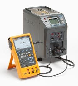
Field checks of temperature sensors can be easily performed with a dry-block or Micro-Bath. For best results, a full calibration of a temperature sensor is performed at the bench. Here are a few tips to consider before getting started:
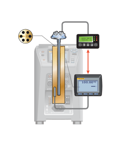
- Dry wells have inserts that are interchangeable and have a variety of hole patterns to accommodate various probe sizes.
- To achieve published performance levels, the insert’s hole size should be no more than a few hundredths of an inch larger than the probe being calibrated.
- Avoid placing fluids in a dry well. If fluids are required, use a Micro-Bath instead.
- If climbing a ladder is required, dry wells are safer than baths, and handheld dry wells may be the most convenient.
How to perform the test:
- Isolate the sensor from the process.
- Fully immerse the sensor into a precision temperature source, such as a dry well or bath capable of covering the required temperature range.
- For best accuracy, also fully immerse a temperature standard into the dry well or bath for comparison. The process version of Field Metrology Wells has a built-in precision readout for the temperature standard.
- To check the calibration of the RTD separately from the control system temperature indicator, disconnect the RTD from the electronics.
- Connect the RTD to a precision instrument capable of measuring resistance. The process version of Field Metrology Wells has the required electronics built in.
- Adjust the temperature of the dry well or bath to each of the test points. With Field Metrology Wells, these test points can be preprogrammed and automated.
- At each test point, record the readings of the temperature standard and RTD.
- If measuring the RTD separate from its measurement electronics, compare the measured resistances to the expected resistance from the applicable temperature table. Otherwise, compare the reading on the instrument display to the reading of the temperature standard, which may be the dry well.
Simulating thermocouples and RTDs
You can use an mV DC source and an mV vs temperature lookup table for simulating thermocouples or a resistance decade box and resistance vs temperature lookup table for simulating RTDs. This method, however, has become outdated with modern temperature calibrators that do the conversion for the user. With modern calibrators, simply select the sensor type to simulate, input the temperature to source and connect to the devices under test. Here are a few tips to consider before getting started:
- When simulating a thermocouple signal from a simulator, always use the correct thermocouple wire for the test, either the exact same TC wire type or a compatible extension wire type.
- When simulating temperature (TCs) using a calibrator with active reference junction compensation, remember the calibrator actively compensates for temperature changes. Changes in ambient temperature should be compensated for automatically.
- When testing 3-wire RTD circuits, make sure to connect all three wires from the sourcing RTD simulator to the device being tested. Shorting out the compensation wire at the transmitter defeats the lead compensation circuit and introduces measurement errors.
How to perform the test when using a thermocouple simulator to test a device with a thermocouple input:
- Disconnect the process measurement sensor and connect the test connection wires in its place.
- Connect the mini connector from the test wires to the TC source connection of the calibrator.
- Connect a digital multimeter or other measurement tool to the tested devices mA output.
- Verify the device's range or span. Apply the 0% temperature value with the simulator and verify with the digital multimeter that the output mA value or voltage is as expected.
- Repeat the test, applying 50% and 100% temperature signals.
- If the measured output of the device is within limits, the test is complete. If not, adjust the device at zero (offset, 0%) and span (gain, 100%).
- Repeat steps 4 and 5 and verify for a correct response.
How to perform the test using an RTD simulator to test a device with an RTD input:
- Connect the calibrator to the device input.
- Connect the calibrator output with the right combination to match the device configuration.
- Use the test procedure for “How to perform the test when using a thermocouple simulator to test a device with a thermocouple input” starting at step 3.
Single-point process temperature verification
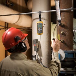
Removing instruments from a process for calibration may not always be possible or practical. In-situ verification at a single point may be the only way to know whether an instrument is performing as expected. A single-point verification is most effective over a narrow temperature range and when combined with other trends and information related to the process and equipment. It also requires the process not to be in a dynamic state of change.
In a single-point process temperature verification, a temperature standard is placed in thermal equilibrium with the sensor of the instrument to be verified without removing it from the process. Usually this is accomplished with a test well that is installed in a location adjacent to the sensor to be tested. The reading from the temperature standard is compared to the reading on the panel meter, controller or transmitter to determine the error and prove the tolerance condition of the loop. Here are a few tips to consider before you get started:
- For this type of application, a battery-powered digital thermometer is usually preferred.
- A graphic display will help you visualize trends, such as stability, quickly and easily.
- Ensure that the probe and readout of your temperature standard have traceable calibration certificates from a competent laboratory.
- If the probe and readout separate from each other, smart connectors, which include probe calibration constants, provide a best practice method of ensuring that the readout is using the correct probe calibration in its temperature readings.
How to perform the test:
- The test well (thermowell) should be within a few inches of the temperature transmitter and sensor assembly to be tested.
- Make sure that the probe of the temperature standard is long enough to reach the bottom of the test well and that air gaps between the probe and well are minimized.
- Wait for the temperature standard to reach the temperature of the test well. This will take a few minutes.
- Check for temperature stability. A graphic digital thermometer makes stability easier to recognize.
- Record the reading from the measurement system and the temperature standard to determine whether the measurement system’s readings are suspect.
Jim Shields is a process calibration product specialist at Fluke Corporation. He has worked in the field of electrical, temperature and pressure measurement for more than 35 years.
About the Author
Jim Shields
process calibration product specialist at Fluke Corporation
Jim Shields is a process calibration product specialist at Fluke Corporation. He has worked in the field of electrical, temperature and pressure measurement for more than 35 years.


