Confusion often surrounds the proper sizing of variable frequency drives (VFDs), and sometimes, knowing when and how to choose one may be difficult. Actually understanding what a VFD does might make this decision easier and the requirements less difficult to understand. VFDs convert input AC power to DC and then invert it back into a modified three-phase AC output. While it may sound simple, it is how this happens that can be quite complicated and is out of the scope of this article. VFDs are designed for many applications (to maintain pressure, flow, dissolved oxygen, level, etc.), but it is important to understand some basics:
- VFDs do not produce horsepower (hp).
- VFDs do not produce torque.
- VFDs supply current that, with the correct voltage and frequency, makes the motor run at the desired speed.
Sizing
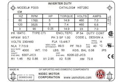
VFD sizing should always be based on motor current and voltage, not hp. Let’s begin with the basics by learning how to read a motor nameplate. The nameplate in Figure 1 shows that motor current is based on the input voltage: volts (V) 230/460, full load amps (FLA) 13.4/6.7. This means the motor uses 13.4 FLA at 230 V AC while only using 6.7 full load amps at 460 V AC.
Motors can be rated for multiple input voltages, but it is extremely important to know the input voltage for the application because VFDs are not rated for multiple voltages and only operate on the voltage for which they are designed, such as 100 to 120 V, 200 to 240 V, 380 to 48 0V or 525 to 600/690 V.
A VFD should never be sized solely on the hp rating of the motor. It is critical that other points be taken into account to ensure proper sizing of the VFD. Let us start with FLAs.
Full load amps
FLAs are the amps on which the motor will draw when operating at full load and full speed. The actual measured FLA may be lower than the nameplate based on the actual loading of the motor (this may be because of a reduced load or a slower speed). It is critical when sizing the VFD to use the motor FLA plus any additional overload that the application may require. This additional overload rating may actually push the VFD selection to the next size, so it is important to use care in sizing the VFD for this additional overload.
Service factor amps
In some pumping applications, the pump manufacturer may size the motor to operate into its service factor to get the pump to maintain flow or head conditions as required. When operating in this condition, it is important to verify the continuous amps required to operate the motor in its new normal conditions. These overload motor amps are used to size the VFD. Sometimes the motor nameplate details the service factor amps of the motor, otherwise it is critical to multiply the running amps by the service factor to ensure proper VFD sizing. The overload rating of the VFD will typically have the VFD running into its intermittent output current rating (which the VFD can run into for one minute out of every 10 minutes, depending on manufacturer), so the VFD should be sized so it is possible to see this overload operation as its continuous amp rating.
For high overload usage of the VFD, it is important to understand how the motor will be used so it can be sized to accommodate the motor overload protection required for more difficult applications such as conveyers, cranes, positive displacement pumps and blowers. These constant torque applications may require 150 to 160 percent overload of motor current when in an overload condition. This overload condition may be required to provide the necessary torque to overcome the starting inertia or during heavy operating conditions in some loads like rock crushers, positive displacement pumps, belt presses, cranes or other applications.
Again, it is critical when sizing the VFD to know as much about the operating conditions as possible. Different manufacturers use different terms when describing the overload operation like high overload, constant torque or automation/industrial VFD to alert the user to the VFD’s overload sizing.
What is normal or standard overload? For applications such as centrifugal pumps, fans, blowers or other variable torque loads, these applications may only require 110 to 120 percent overload current for one minute. This overload may be required to provide the necessary torque to overcome the starting inertia or operation during heavy conditions in some loads like pumping solids or other viscous materials. Most pumping and fan VFDs today are sized with variable torque as their primary sizing.
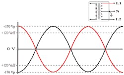
Figure 2. Waveform of a 240/120-Volt single-phase system.
Other pitfalls
It is also important to know the type of motor in the installation. For example, be careful when operating a submersible motor. Submersible motors are not National Electrical Manufacturers Association (NEMA) B-type motors and typically draw more current per hp than conventional NEMA B-type motors. What about low-rpm motors? These motors sometimes require more current to operate. Equipment alignment will always be better if the correct nameplate motor current is determined and the VFD is sized based on those facts.
Single-phase input is another useful application of a VFD for phase conversion. When only single-phase power is available, some VFDs can use single-phase input power to provide three-phase output power and operate a three-phase motor. Some manufacturers provide specific VFD units designed for this while others simply oversize the VFD and derate for this feature. Derating the VFD may not be fully UL listed. Users should be cautious in their search for VFDs and purchase fully tested UL VFDs certified on single-phase inputs with three-phase outputs.
High-altitude installations also require special attention. As the air thins with higher altitude, the ability of the air to transfer heat out of the VFD is reduced. The higher the altitude, the less heat the VFD can exhaust, requiring a derating or reduction in its ability to produce output current. This is different by manufacturer and size, so for the best information, visit the VFD manufacturer’s website or call the tech support hotline.
Higher ambient temperature can also affect the VFD size since heat dissipation is the big design issue with VFDs. The higher the ambient air temperature, the hotter it is when running the VFD. The issue is that the VFD is unable to cool itself as it generates heat while producing current to run the motor. With a high ambient temperature, the VFD is unable to dissipate the generated heat it needs to dissipate and keep itself cool. The sizing may require the need to derate for higher ambient temperature or cool the VFD with cooler air. An air conditioner is not always the solution. Sometimes an exhaust fan may change enough air to allow the VFD to operate satisfactorily. The derate value varies by manufacturer and by size, so no good rule applies other than to visit the manufacturer’s website or call the tech support hotline.
Low ambient temperature can also be a potential pitfall. VFDs need a certain amount of heat to keep all components operating at their optimal designs. The low thermal rating needs to be taken into account when mounting VFDs in unconditioned or outside installations. Capacitors, insulated-gate bipolar transistors and LCD displays are some of the components that do not operate well in below-freezing temperatures or when frozen. If a VFD is unpowered, has been in a below-freezing temperature and is frozen, it is crucial that the drive be warmed up before powering because this extreme condition could cause the capacitors to explode.
It may seem like there are a lot of things to keep track of, but VFD manufacturers are constantly trying to make VFDs easier to size, install and program. And with the usage of drives on more and more motors, more of them will likely be present in homes and at work. Additional questions about proper sizing should be directed to local VFD suppliers for help.
Jeff Bergman is global key account manager for Danfoss Drives. He may be reached at [email protected].
Sean Fitzpatrick is global key account manager for Danfoss Drives. He may be reached at sean.fitzpatrick@
danfoss.com.

