How to achieve a reliable, long-running pump system
The secret to a pumping system that performs reliably throughout its useful life is not really so secret after all. Dependable pumping system performance is attainable by anyone — so long as they follow some simple, straightforward guidelines.
Rule No. 1: Install the pumping system correctly
The most common cause of pumping system operating problems is not a malfunctioning inverter duty motor or variable frequency drive (VFD). Rather, pumping system problems can most often be traced to improper installation.
A little background: A VFD is an adjustable-speed drive that controls alternating current motor speed and torque by varying motor input frequency and voltage. Many motor manufacturers offer motors designed to run on VFDs because VFDs make it possible to maintain peak efficiency when output demand changes by adjusting the speed of the system.
These motors are specially designed to be operated when powered by a VFD’s pulse width modulated (PWM) power waveform. While it is an efficient method of motor speed control, a PWM wave form can, among other things, cause a motor winding to experience voltage spikes that are well above the rated voltage of the motor.
The problem is that installers often do not understand how to protect a motor from the potentially harmful effects a VFD can produce, or how to reduce these effects in a pumping system. Many do not realize that motors used with a VFD require a few extra protections. These include:
They need additional winding protection. — To protect against voltage spikes, these motors require additional winding protection. According to NEMA MG1 Part 31, motors with voltage ratings of 600 volts (V) or less that are used on VFDs should have windings that protect, at minimum, against a voltage spike of 3.1 times the rated voltage. For motors with voltage ratings greater than 600 V, the minimum is 2.04 times the motor’s rated voltage. It is important to check with the manufacturer. Some now provide these protections as standard features, while some do not.
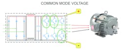
Bearings should be protected with shaft grounding. — Windings are not the only components of a motor impacted by PWM waveforms. An electric motor’s bearings must also be protected from the charge imbalance that can build up between the rotor and stator because of PWM waveform. Known as common mode voltage (CMV), this differential charge needs to be balanced to prevent motor damage.
Figure 1. Common mode voltage. To make a variable speed pumping system robust and operate reliably, it takes more than assembling a pump, motor and VFD together.
To understand CMV, think about what happens when someone scoots across a carpet in socks and then touches a doorknob. The small shock the person experiences is nature’s way of rectifying an unbalance in electrical charges by finding the person to be the lowest-resistance path to the ground. This is also a small-scale version of what happens within the bearings of a motor that is not installed and protected correctly.
If the bearings are not isolated from the shaft and the system is incorrectly grounded, the bearings provide the path of least resistance that a motor seeks to balance the charge. When this balance happens within a bearing, pieces of bearing material can dislodge while the motor is running, which can severely damage the bearing, or at least cause noise, heat and premature failure over time.
One way to prevent the CMV phenomenon is to give the motor a low-resistance path to balance the charge between the rotor and stator. This is commonly achieved by adding a shaft-grounding device to the motor, as well as grounding the motor itself. On larger motors such as those 100 hp and higher, additional protection can be gained by insulating the bearing opposite the shaft grounding ring to eliminate circulating currents.
Again, some manufacturers include these as standard features on inverter duty motors. Nidec, for example, includes them on all vertical motors because it believes they are necessary to ensure motor reliability on invertor duty applications. It always pays to ask.
Rule No. 2: Choose the correct cabling & ground it properly
CMV and other issues created by the interaction between the motor and VFD can be mitigated by taking other precautions during installation, including:
Power cable selection — The power cables that run from the VFD to the motor should be shielded and specifically rated for use with a VFD. Check with the manufacturer to ensure they are the recommended size for the system’s voltage and current limits.
And remember: When choosing grounding cable, you get what you pay for. Some system installers may be tempted to use smaller or improperly shielded cable because the recommended one is more expensive or they have an alternative cable on hand. They may not realize the damaging effects that improperly sized cable can have on a motor. The correct cable will always cost less than a replacement motor and is worth it in the long run.
The distance between the motor and drive matters, too. As the distance increases, the damaging effects are amplified. While it is common to locate a VFD on one floor and the motor on another, operators are wise to locate them in as close proximity to each other as possible.
Grounding — The motor will not be completely protected if it alone is grounded. The VFD produces high-frequency noise that needs to be grounded back to the drive as well. That involves more than running a cable back to the common ground on the drive. The motor should be grounded back to the drive using a braided type of grounding wire that is, at minimum, the same size as a single-power lead and runs in the same conduit as the power leads.
Conduit selection — The conduit used to house these power leads and the grounding wire should be metal. Also, the conduit should be connected to the motor and drive without isolating either.
In other words, PVC, plastic or other insulating materials should not be used to connect metal conduit into a drive or motor terminal box. If any of these materials are used, it is critical that the metal conduit that carries the power leads and ground cable is properly connected to the grounding circuit. The VFD manufacturer may be able to recommend filtering options that can reduce risk even further.
Rule No. 3: Approach the drive & motor as a single system
The reason some motor manufacturers now add extra protection on the winding, shaft grounding and insulated bearings is simple: They cannot predict where, how or when these components will be installed. But a sure-fire way exists to mitigate these effects before they have a chance to start, while also achieving a reliable, robust and a long-running variable speed pumping system. And that is by installing the motor and VFD as a system that has been designed to mitigate issues caused by using PWM power waveforms.
Proper installation, in other words, requires more than grounding the motor, grounding the drive and connecting them. It requires taking a systems approach that considers everything from the proximity of the motor and drive, to the filters, grounds and other steps that can be taken to avoid voltage peaks.
If the motor is grounded back to the drive, and the wire, conduit and filter are correctly sized, the result should be a variable speed drive system that runs to specification.
Patrick Hogg is application engineering manager of General Industry & Integral Horsepower Pumping for Nidec Motor Corporation. He may be contacted at [email protected].

