Improved precision and reliability of flow measurement ensures accurate custody transfers
It is an understatement to say that the global energy industry has been going through major changes in the last few years. The use of hydrogen (H2) as a means to store and transfer energy continues to grow, and geopolitical conflicts have caused major disruptions to natural gas distribution. As there are new relationships among buyers and sellers, it might be beneficial to review technologies for custody transfer of natural gas, specifically how it is measured using flow meters when changing ownership.
Such custody transfer happens multiple times, but the same concept applies in all cases. A flow-totalizing device calculates the amount of gas transferred, which is used for the resulting commercial transaction. The buyer and seller must accept the accuracy so both sides are satisfied.
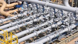
By the time natural gas produced in the Permian Basin gets liquified and sent to the Brunsbüttel LNG Terminal near Hamburg, Germany, it has probably changed ownership — perhaps eight times or more — between various pipelines and processors. Each time it changes hands, that is a point of custody transfer (Figure 1), and all parties involved must agree on how much product was moved at each point.
Accuracy is paramount, given the volumes and values involved. For example, an error as small as 0.25% equates to financial risk of nearly $500,000 per year on 3 million standard cubic meters per day at $5 per million BTU. Measurement errors lead to financial exposure and disagreements, costly in both money and time. For most industrial applications, a flow meter with accuracy of ±0.25% is exceptionally precise, but the higher the annual economic trading value, the more accuracy required from the flow meter and corresponding meter assembly.
So, what are the specific requirements for natural gas custody transfer?
- Size: pipes can be anywhere between 3 and 42 inches, so scalability is critical.
- Accuracy: to meet the highest accuracy class for gas measurement, international metrology standards call for a maximum allowable shift in accuracy of ±0.167% compared to an international reference standard with disturbed flow conditions present.
- Turndown: this is difficult to quantify specifically, but the seasonality of natural gas consumption causes throughput of most facilities to go up and down. Flow meters generally have a sweet spot where their accuracy is highest, so if the flow moves out of that range, accuracy suffers. Sites usually compensate for this by using multiple meters in parallel to avoid having to reduce flow below tolerable levels.
Problems measuring gas flow
Measuring gas flow is challenging primarily because of compressibility, which eliminates many of the technologies suitable for liquid measurement. The most common approaches for gas flow measurement are:
- Thermal mass
- Coriolis
- Turbine
- Differential pressure (DP)
- Ultrasonic
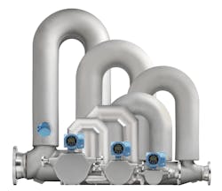
If we think in terms of custody transfer at pipeline scale, we can narrow the list down. Thermal mass sensors cannot handle large lines sizes or deliver the required accuracy. Coriolis mass flow meters (Figure 2) are excellent for measuring gas flows, and are frequently used for custody transfer. They are immune to many of the challenges discussed later, but they are very expensive, particularly in large sizes. They also create a pressure drop that can make moving the gas more expensive. The largest size is around 16 inches with most manufacturers topping out their offerings at 10 inches. The larger the size, the larger the U-shaped pipe which is more difficult and expensive to install. Straight pipe versions exist but they are less accurate. Coriolis meters can cover a wide range of applications, but other technologies are needed for line sizes above 16 inches, as often found in gas transmission and distribution pipelines.
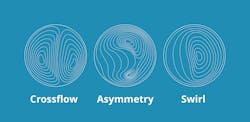
There are operational and fluid-flow characteristics that complicate measurement, and they are made worse by the sheer size of these installations. Pipelines often introduce process issues, such as pressure pulsations, noise from valves and blockages caused by contaminants. The more basic problem of fluid-flow physics is profiling, which recognizes that fluid velocity is highest at the center, and slows closer to the walls, although other profiles can also form (Figure 3). Disturbed flow is also introduced by pipe elbows, valves and other fittings common to metering skids. These factors affect all three of the meter types under discussion, so users create mitigation solutions.
Turbine flowmeters
This technology offers some appealing capabilities but is not without its drawbacks. Pipe sizes are limited, with 24-inch versions the largest, depending on the manufacturer. It has high accuracy under favorable operating conditions with good repeatability, and it can be calibrated to zero-in the value. Moreover, it is capable of a high turndown ratio, often up to 40:1.
On the other hand, it is a mechanical device with a spinning rotor and gear train, and it therefore requires maintenance. It can also drift over time, reducing accuracy. Models available today have very sophisticated bearings with long service life, but if there are contaminants in the gas stream, these can interfere with smooth operation. Increasing bearing friction due to wear can slow rotation, making the unit read low if this condition is not detected and fixed.
The turbine itself creates a small pressure drop, and the meter needs a minimally disturbed flow to ensure the highest accuracy. Some applications remove flow disturbances with a flow-conditioning plate, a disk with multiple orifices sandwiched between a flanged pipe joint or built into the flow meter enclosure. This causes enough pressure drop to force a more equalized volume of gas across the full diameter, resulting in a more stable flow profile, at least temporarily, ahead of the measuring point. Of course, it creates another point of pressure drop.
DP metering
This is one of the oldest flow measuring approaches, and it is also the most commonly applied in general industry. It is scalable to large pipeline diameters, so there is no limitation in that respect. It does require a pressure drop, so there is an energy-loss consideration. The amount of pressure drop determines the practical turn-down ratio, so in most situations a modest turn-down ratio (10:1) is the maximum practical limit to minimize pressure loss.
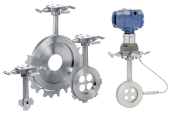
Disturbed flow is also a major factor, so DP flow meters with a concentric, sharp-edge orifice plates (Figure 4) require long upstream pipe lengths depending on the beta ratio. Achieving the highest accuracy can require as many as 45 meters of straight pipe, and typically at least 20 meters of straight, smooth pipe upstream from the meter, and one-third to one-half that length downstream. Naturally, when working with large pipe diameters, this requires a great deal of pipe and increases the skid size, or the installation area requirements. One solution is to use an orifice plate with multiple holes rather than just one, shortening the overall straight pipe length requirement. Another approach is to use a flow-conditioning plate upstream of the meter, but this creates another point of pressure drop.
Ultrasonic flowmeters
This technology employs the characteristic effects of sound projected through a moving fluid. A sound pulse is transmitted upstream and downstream across the pipe from a pair of transducers that act as both transmitters and receivers. The pulse travels through the moving fluid, and its transit time differential between upstream and downstream transit times indicates fluid velocity. This has several key benefits:
- There is no pressure drop since there is no need for a pipe restriction.
- It is unaffected by size, so it works well for small pipe sizes and the largest pipe sizes, with 2- to 42-inch multi-path units available, depending on the manufacturer.
- Multi-path designs, with sound passing through multiple cross sections of the pipe for measurement of more of the flow profile, helps minimize velocity effects.
- It is still affected by flow disturbances, but newer designs have very low sensitivity and can be installed with only three to five diameters of upstream piping while maintaining the highest accuracy.
- It can measure bi-directional flow.
- It can measure H2, natural gas and a blend of the two.
- It withstands harsh environments with hydrogen sulfide (H2S), glycols, high temperatures and pressures, and some can even measure very high concentrations of carbon dioxide (CO2).
Multiple sensors in one unit
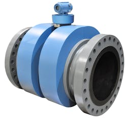
Flow meters designed for pipeline use are normally configured as flanged spool sections (Figure 5) so they can be bolted into an appropriate location. Ultrasonic flow meters have a unique characteristic as they can be built with multiple sensors. The simplest use a single transducer/sensor pair and send the pulse across the pipe or bounce it off the opposite side. This is often sufficient for basic process monitoring, but it cannot deliver the degree of accuracy necessary for custody transfer.
Ultrasonic flow meters can be equipped with multiple transducer/sensor pairs, and this capability introduces a unique way to maintain accuracy even where piping configurations introduce flow disturbances. Basic designs use two pairs, and more advanced models use four paths to eight paths to minimize velocity effects. Some models reduce uncertainty with a secondary integral check measurement.
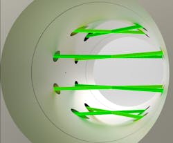
Some of the newest ultrasonic flow meters use eight transducer/receiver pairs, each placed to read velocity at four positions, with the first set of four set in the mirror image of the second within the body, with flow in either direction (Figure 6). Using this eight-path approach, it is possible to characterize the flow profile to create the most accurate picture of gas movement and volume for exceptional measuring precision. Each position provides two chords across the pipe diameter, so there are eight measurements taken over 32 milliseconds.
This sounds complex, but internal data processing converts the raw data into a detailed flow picture, with diagnostic capabilities confirming the validity of each reading, as well as providing operators with significant insight into their process.
Simplified installation
Since the eight-path measuring approach is much less affected by a disturbed flow profile, it is easier to install because it does not require long sections of straight pipe or flow conditioning plates. The American Gas Association (AGA) has updated its installation recommendations to include diagrams of installations with shorter upstream pipe lengths (with and without flow conditioning) provided the manufacturer can demonstrate installation accuracy. It acknowledges that newer manufacturer-recommended options are valid and can ensure accuracy.
A fast-growing strategy
The advantages of ultrasonic flow measurement technology have made it a rapidly growing solution for natural gas measurement in all conditions, thanks to its wide operating envelope, including measurement of many different media in a variety of industries and applications:
- Clean, dry gas
- H2
- Well-head output
- Wet gas
- Biogas
- CO2
- LNG
Sophisticated signal processing and advanced diagnostics provide self-verification capabilities for robust operation and warnings of developing problems. With all the changes in the oil and gas industry, the dependability of these new technologies provides the means for companies to ensure easy, accurate custody transfers, even with ongoing conditions so uncertain.
There remain a number of options for measuring gas flow, both in terms of different technologies, and different types of meters within each technology family. Therefore, end users should consult with a knowledgeable vendor offering many different types of flow meters during their selection process to ensure the best choice for their application.
Lonna Dickenson is the product director for the Emerson gas and liquid Rosemount ultrasonic flow meters. She is the global product leader for ultrasonic technology at Emerson, where she has led vision, strategy, and product development for the fiscal gas ultrasonic portfolio over the past 11 years in Emerson’s Flow Technology Group.
Emerson
About the Author
Lonna Dickenson
Product director for the Emerson gas and liquid Rosemount ultrasonic flow meters.
Lonna Dickenson is the product director for the Emerson gas and liquid Rosemount ultrasonic flow meters. She is the global product leader for ultrasonic technology at Emerson, where she has led vision, strategy, and product development for the fiscal gas ultrasonic portfolio over the past 11 years in Emerson’s Flow Technology Group. Dickenson holds a Bachelor of Science from the University of Texas at Austin, and an MBA from Rice University in Houston.
